Produkt ähnlich wie:
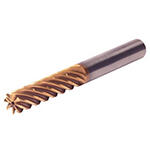
HARVI™ IV • Square End • 8 Flutes • Internal Coolant • Chipbreaker • Plain Shank • Inch
HARVI™ IV Eight Flute End Mill for Roughing and Finishing
Covering the Broadest Range of Applications and Materials
Material Nummer7102839
ISO Katalog NummerHA4R8SE0375R100HADANSI Katalog NummerHA4R8SE0375R100HAD
- P Stahl
- M Rostfreier Stahl
- S Hochwarmfeste Legierungen
- H Gehärtete Werkstoffe
Trochoidal Milling
100665610
107038547
Spiralförmiges Interpolieren
Schräg-Eintauchfräsen Ins Volle
Umfangfräsen/Schulterfräsen: Ebene Stirnfläche
Auskammern
Sending to {{cadTool}} in progress...
Downloaded file will be available after import in the {{cadTool}} tool library.
| Material Nummer | 7102839 |
| ISO Katalog Nummer | HA4R8SE0375R100HAD |
| ANSI Katalog Nummer | HA4R8SE0375R100HAD |
| Sorte | KCSM15A |
| Aufnahmeart Maschinenseite | Straight-Cylindrical |
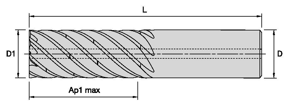
| [D1] Effektiver Schneidendurchmesser | 9.525 mm |
| [D1] Effektiver Schneidendurchmesser | 0.375 in |
| [D] Adapter/Schaft/Bohrungsdurchmesser | 9.525 mm |
| [D] Adapter/Schaft/Bohrungsdurchmesser | 0.375 in |
| [AP1MAX] 1. maximale Schnitttiefe | 25.4 mm |
| [AP1MAX] 1. maximale Schnitttiefe | 1 in |
| [L3] Nutzbare Länge | 29.718 mm |
| [L3] Nutzbare Länge | 1.17 in |
| [L] Gesamtlänge | 76.2 mm |
| [L] Gesamtlänge | 3 in |
| [Z] Anzahl der Spannuten | 8 |
Werkstoffe
- Stahl
- Rostfreier Stahl
- Hochwarmfeste Legierungen
- Gehärtete Werkstoffe
Uses and application
Trochoidal Milling
100665610
107038547
Spiralförmiges Interpolieren
Schräg-Eintauchfräsen Ins Volle
Umfangfräsen/Schulterfräsen: Ebene Stirnfläche
Auskammern
Features and benefits
- Single tool for roughing and finishing to reduce tool setups.
- Proprietary core and flute design with optimum flute spacing for perfect chip formation and highest tool rigidity.
- Developed for highest productivity in titanium, high-temperature alloys, and stainless steels.
- With chip breakers for optimized chip evacuation.
Lösung erstellen, um Vorschübe und Geschwindigkeiten zu berechnen
Nachdem Sie eine Lösung erstellt haben, wählen Sie einfach das Symbol für Vorschübe und Geschwindigkeiten und unser System gibt Ihnen Empfehlungen. Sie können die Informationen anpassen, indem Sie Ihre Maschine und Spezifikationen hinzufügen oder Anpassungen mithilfe der Schieberegler vornehmen.
Anwendungsdaten
| Adjustment factors for speed (Vc) and feed (Fz) • METRIC | |||||||
| Maximum cutting width (Ae) for given cutting depth (Ap) | |||||||
| Ap | ≤.125 x D1 | >.125xD1 ≤ .5xD1 | >.5xD1 ≤ 1xD1 | >1xD1 ≤ 2xD1 | >2xD1 ≤ 3xD1 | >3xD1 ≤ 4xD1 | >4 x D1 |
| Max Ae | 100% x D1 | 50% x D1 x KAp | 40% x D1 x KAp | 30% x D1 x KAp | 20% x D1 x KAp | 15% x D1 x KAp | 10% x D1 x KAp |
| Note: KAp value is given on the Speed and Feed table, according to the type of workpiece material selected. | |||||||
| Adjustment factors for speed (Vc) and feed (Fz) • METRIC | ||||||||||
| Ae/D1 | ≤2% | >2% ≤ 5% | >5 ≤ 7.5% | >7.5% ≤ 10% | >10% ≤ 15% | >15% ≤ 20% | >20% ≤ 30% | >30% ≤ 40% | >40% ≤ 50% | >50% ≤ 100% |
| Kv | 3 | 2.5 | 1.9 | 1.4 | 1.35 | 1.3 | 1.2 | 1.1 | 1 | 0.9 |
| KFz | 3.28 | 2.3 | 1.95 | 1.7 | 1.5 | 1.25 | 1.09 | 1.02 | 1 | 1 |
| Note: Identify the radial engagement per percentage of the tool diameter (Ae/D1). That column will give you the factor to multiply the Base SMF and Base IPT on the Speed and Feed original table Kv = Factor to multiply the Speed by KFz = Factor to multiply the Feed by | ||||||||||
| To calculate application specific cutting data, please use KAp, Kv, and Kfz from tables above for adaption of cutting speeds and feeds respectively: Maximum Ae=(Ap1Max/D1) * KAp * D1 Vc new = Vc * Kv IPT new = IPT * KFz | Sample Calculation Material: S4 D1: 25 mm Ap: 2xD1 Max Ae: 30% x KAp x D1 --- 30% * 0.7 * D1 = 21%xD1 SFM: Base x Kv --- 45 * 1.2 = 54 IPT: Base x KFz --- 0.081 * 1.09 = 0.088 | Final cutting data recommendation: Max Ae = 0.3 * 0.7 * 25 = 5.25 mm Vc new = 45 * 1.2 = 54 m/min IPT new = 0.081 * 1.09 = 0.088 mm/th | ||||||||
| Table for Feed and Speed Calculation with Adjustment Factor • METRIC | ||||||||
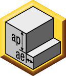 | Schulterfräsen (A) | KCSM15A | Empfohlener Vorschub pro Zahn (fz = mm/Zahn) zum Eckfräaen mit ae/D=10% | |||||
| Werkstoffgruppe | Max Ae Factor (KAp) | Schnittgeschwindigkeit | 10 | 12 | 16 | 20 | 25 | |
| P | 3 | 1 | 130 | 0.049 | 0.055 | 0.067 | 0.080 | 0.095 |
| 4 | 1 | 100 | 0.044 | 0.049 | 0.059 | 0.069 | 0.081 | |
| 5 | 0.8 | 65 | 0.038 | 0.043 | 0.053 | 0.063 | 0.076 | |
| 6 | 0.7 | 50 | 0.032 | 0.036 | 0.043 | 0.050 | 0.060 | |
| M | 1 | 1 | 80 | 0.049 | 0.055 | 0.067 | 0.080 | 0.095 |
| 2 | 0.8 | 60 | 0.038 | 0.043 | 0.053 | 0.063 | 0.076 | |
| 3 | 0.8 | 60 | 0.032 | 0.036 | 0.043 | 0.050 | 0.060 | |
| S | 1 | 0.5 | 50 | 0.049 | 0.055 | 0.067 | 0.080 | 0.095 |
| 2 | 0.5 | 30 | 0.038 | 0.043 | 0.053 | 0.063 | 0.076 | |
| 3 | 0.5 | 25 | 0.026 | 0.030 | 0.036 | 0.043 | 0.051 | |
| 4 | 0.7 | 45 | 0.041 | 0.051 | 0.061 | 0.069 | 0.081 | |
| H | 1 | 0.8 | 80 | 0.044 | 0.049 | 0.059 | 0.069 | 0.081 |
| 2 | 0.5 | 70 | 0.037 | 0.041 | 0.050 | 0.059 | 0.070 | |
| These guidelines may require variations to achieve optimum results. Above parameters are based on ideal conditions. For smaller taper machining centers, please adjust parameters accordingly on | ||||||||
| Adjustment factors for speed (Vc) and feed (Fz) • INCH | ||||||||||
| Ae/D1 | ≤2% | >2% ≤ 5% | >5 ≤ 7.5% | >7.5% ≤ 10% | >10% ≤ 15% | >15% ≤ 20% | >20% ≤ 30% | >30% ≤ 40% | >40% ≤ 50% | >50% ≤ 100% |
| Kv | 3 | 2.5 | 1.9 | 1.4 | 1.35 | 1.3 | 1.2 | 1.1 | 1 | 0.9 |
| KFz | 3.28 | 2.3 | 1.95 | 1.7 | 1.5 | 1.25 | 1.09 | 1.02 | 1 | 1 |
| Note: Identify the radial engagement per percentage of the tool diameter (Ae/D1). That column will give you the factor to multiply the Base SMF and Base IPT on the Speed and Feed original table Kv = Factor to multiply the Speed by KFz = Factor to multiply the Feed by | ||||||||||
| To calculate application specific cutting data, please use KAp, Kv, and Kfz from tables above for adaption of cutting speeds and feeds respectively: Maximum Ae=(Ap1Max/D1) * KAp * D1 Vc new = Vc * Kv IPT new = IPT * KFz | Sample Calculation Material: S4 D1: 25 mm Ap: 2xD1 Max Ae: 30% x KAp x D1 --- 30% * 0.7 * D1 = 21%xD1 SFM: Base x Kv --- 45 * 1.2 = 54 IPT: Base x KFz --- 0.081 * 1.09 = 0.088 | Final cutting data recommendation: Max Ae = 0.3 * 0.7 * 25 = 5.25 mm Vc new = 45 * 1.2 = 54 m/min IPT new = 0.081 * 1.09 = 0.088 mm/th | ||||||||
| Table for Feed and Speed Calculation with Adjustment Factor • INCH | |||||||||
 | Schulterfräsen (A) | KCSM15A | Recommended feed per tooth (fz=IPT) for side milling | ||||||
| frac. | 3/8 | 1/2 | 5/8 | 3/4 | 1 | ||||
| Werkstoffgruppe | Max Ae Factor (KAp) | Schnittgeschwindigkeit | dec. | 0.375 | 0.500 | 0.625 | 0.750 | 1 | |
| P | 3 | 1 | 420 | IPT | 0.0018 | 0.0023 | 0.0027 | 0.003 | 0.0037 |
| 4 | 1 | 320 | IPT | 0.0016 | 0.0021 | 0.0024 | 0.0026 | 0.0031 | |
| 5 | 0.8 | 210 | IPT | 0.0014 | 0.0018 | 0.0022 | 0.0024 | 0.0029 | |
| 6 | 0.7 | 160 | IPT | 0.0012 | 0.0015 | 0.0018 | 0.0019 | 0.0022 | |
| M | 1 | 1 | 275 | IPT | 0.0018 | 0.0023 | 0.0027 | 0.003 | 0.0037 |
| 2 | 0.8 | 200 | IPT | 0.0014 | 0.0018 | 0.0022 | 0.0024 | 0.0029 | |
| 3 | 0.8 | 200 | IPT | 0.0012 | 0.0015 | 0.0018 | 0.0019 | 0.0022 | |
| S | 1 | 0.5 | 160 | IPT | 0.0018 | 0.0023 | 0.0027 | 0.003 | 0.0037 |
| 2 | 0.5 | 100 | IPT | 0.0014 | 0.0018 | 0.0022 | 0.0024 | 0.0029 | |
| 3 | 0.5 | 80 | IPT | 0.001 | 0.0013 | 0.0014 | 0.0016 | 0.002 | |
| 4 | 0.7 | 160 | IPT | 0.0016 | 0.002 | 0.0024 | 0.0027 | 0.0032 | |
| H | 1 | 0.8 | 260 | IPT | 0.0016 | 0.0021 | 0.0024 | 0.0026 | 0.0031 |
| 2 | 0.5 | 230 | IPT | 0.0014 | 0.0018 | 0.002 | 0.0022 | 0.0026 | |
| These guidelines may require variations to achieve optimum results. Above parameters are based on ideal conditions. For smaller taper machining centers, please adjust parameters accordingly on | |||||||||
| Adjustment factors for speed (Vc) and feed (Fz) • INCH | |||||||
| Maximum cutting width (Ae) for given cutting depth (Ap) | |||||||
| Ap | ≤.125 x D1 | >.125xD1 ≤ .5xD1 | >.5xD1 ≤ 1xD1 | >1xD1 ≤ 2xD1 | >2xD1 ≤ 3xD1 | >3xD1 ≤ 4xD1 | >4 x D1 |
| Max Ae | 100% x D1 | 50% x D1 x KAp | 40% x D1 x KAp | 30% x D1 x KAp | 20% x D1 x KAp | 15% x D1 x KAp | 10% x D1 x KAp |
| Note: KAp value is given on the Speed and Feed table, according to the type of workpiece material selected. | |||||||
TechnicalInfo
| Angle of engagement (phi°) relative to cutting width (Ae) |  | |||||||||
| ae | 2% | 5% | 7.50% | 10% | 15% | 20% | 30% | 40% | 50% | 100% |
| phi - angle of engagement | 16.26 | 25.84 | 31.79 | 36.87 | 45.57 | 53.13 | 66.42 | 78.46 | 90 | 180 |
I have read and accepted the Terms & Conditions of use
CAD Drawings Models
Can’t find the file type you’re looking for?
Product data
