List Price
/each
Discount
Your Price
/each
Sold in pkg. of 0Adjusted to meet the minimum package size.
Minimum qty: 0Adjusted to meet the minimum quantity requirement.
In StockThis item is no longer availableLonger Delivery


Downloaded file will be available after import in the {{cadTool}} tool library.
| Material Number | 1130686 |
| ISO Catalog ID | 17X1R022B16STN16N |
| ANSI Catalog ID | 17X1R022B16STN16N |
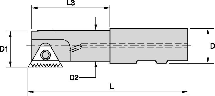
| [D1] Effective Cutting Diameter | 17 mm |
| [D1] Effective Cutting Diameter | 0.6692 in |
| [D] Adapter / Shank / Bore Diameter | 16 mm |
| [D] Adapter / Shank / Bore Diameter | 0.6299 in |
| [D2] Maximum Body Diameter | 13.6 mm |
| [D2] Maximum Body Diameter | 0.5354 in |
| [L] Overall Length | 90 mm |
| [L] Overall Length | 3.5433 in |
| [L3] Usable Length | 22 mm |
| [L3] Usable Length | 0.866 in |
| Number of Inserts | 1 |
| Max RPM | 25750 |
| Gage Insert | STN16 |
Create Solution to calculate Feeds and Speeds
After creating a solution just choose the Feeds & Speeds icon and our system will provide recommendations. You can customize the information by adding your machine and specifications or make adjustments using the sliders.
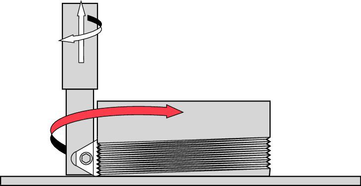 |  |
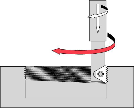
| right-hand thread... conventional milling | left-hand thread... conventional milling |
 | 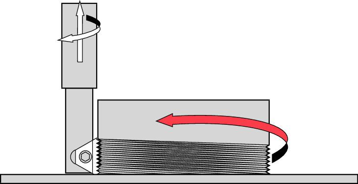 |
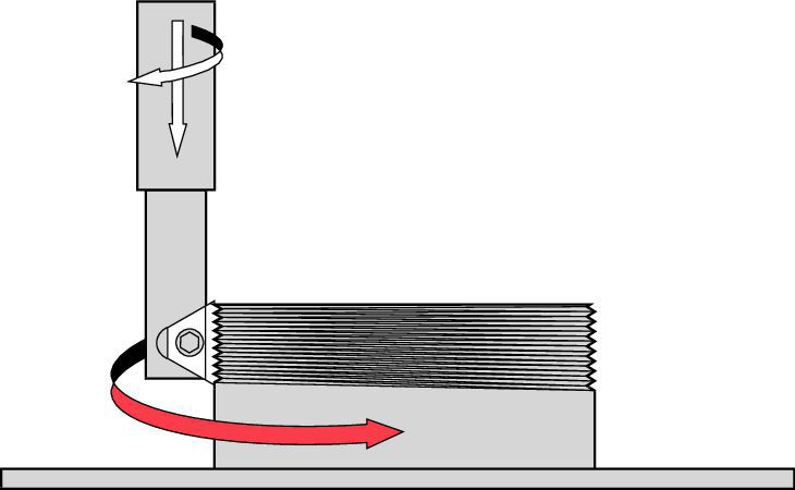
| right-hand thread... climb milling | left-hand thread... climb milling |
 | 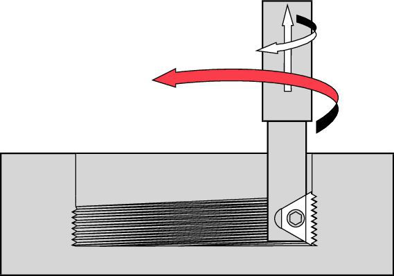 |
| right-hand thread... conventional milling | left-hand thread... conventional milling |
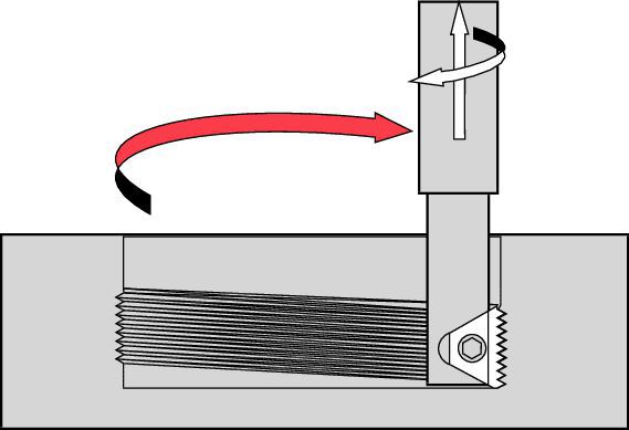 |  |
| right-hand thread... climb milling | left-hand thread... climb milling |
| cutter | TPI | 48 | 32 | 24 | 20 | 16 | 12 | 10 | 8 | 7 | 6 | 5.5 | 5 | 4.5 | 4.5 | 4 | 4 |
| pitch mm | 0,5 | 0,75 | 1,0 | 1,25 | 1,5 | 2,0 | 2,5 | 3,0 | 3,5 | 4,0 | 4,5 | 5,0 | 5,5 | – | 6,0 | – | |
| cutter diameter (D1) | minimum bore diameter (D) (inches) | ||||||||||||||||
| K035TM1RW050-STN10 | .35 | .374 | .394 | .421 | .449 | ||||||||||||
| K045TM1RW050-STN11N | .45 | .472 | .492 | .520 | .547 | .571 | |||||||||||
| K049TM1RW037LT11S | .49 | .512 | .531 | .559 | .587 | .610 | |||||||||||
| K061TM1RW062-STN16T | .61 | .630 | .650 | .667 | .705 | .728 | .768 | ||||||||||
| K067TM2RW075-STN11D | .67 | .693 | .717 | .748 | .772 | .787 | .827 | ||||||||||
| K075TM1RW075-STN16T | .75 | .776 | .803 | .827 | .850 | .866 | .906 | ||||||||||
| K079TM1RW075-STN16N | .79 | .815 | .843 | .866 | .890 | .906 | .945 | ||||||||||
| K087TM1RW100-STN16L | .87 | .893 | .921 | .945 | .969 | .984 | 1.024 | ||||||||||
| K102TM2RW100-STN16D | 1.02 | 1.051 | 1.079 | 1.102 | 1.130 | 1.154 | 1.193 | ||||||||||
| K118TM1RW100-STN27N | 1.18 | 1.209 | 1.236 | 1.260 | 1.291 | 1.319 | 1.362 | 1.441 | 1.535 | 1.654 | 1.772 | 1.890 | |||||
| K146TM1RW125-STN27N | 1.46 | 1.496 | 1.520 | 1.555 | 1.591 | 1.614 | 1.654 | 1.732 | 1.830 | 1.929 | 2.047 | 2.185 | |||||
| K165TM2RW125-STN27D | 1.65 | 1.701 | 1.724 | 1.772 | 1.811 | 1.831 | 1.866 | 1.929 | 2.047 | 2.146 | 2.268 | 2.401 | |||||
| – | 1.38 (UN) | – | – | – | – | – | – | – | – | – | 1.969 | – | 1.843 | – | 1.756 | – | 2.228 |
| – | 1.38 (ISO) | – | – | – | – | – | – | – | – | – | 1.969 | 2.102 | 1.673 | 1.969 | – | 2.264 | – |
| – | 1.38 (BSW) | – | – | – | – | – | – | – | – | – | 1.961 | – | 1.831 | – | 1.866 | – | – |
| cutter | TPI | 48 | 32 | 24 | 20 | 16 | 12 | 10 | 8 | 7 | 6 | 5.5 | 5 | 4.5 | 4.5 | 4 | 4 |
| pitch mm | 0,5 | 0,75 | 1,0 | 1,25 | 1,5 | 2,0 | 2,5 | 3,0 | 3,5 | 4,0 | 4,5 | 5,0 | 5,5 | – | 6,0 | – | |
| cutter diameter (D1 mm) | minimum bore diameter (D) (mm) | ||||||||||||||||
| K035TM1RW050-STN10 | 8,89 | 9,50 | 10,01 | 10,69 | 11,40 | ||||||||||||
| K045TM1RW050-STN11N | 11,43 | 11,99 | 12,50 | 13,21 | 13,89 | 14,50 | |||||||||||
| K049TM1RW037LT11S | 12,45 | 13,00 | 13,49 | 14,20 | 14,91 | 15,49 | |||||||||||
| K061TM1RW062-STN16T | 15,49 | 16,00 | 16,51 | 16,94 | 17,91 | 18,49 | 19,51 | ||||||||||
| K067TM2RW075-STN11D | 17,02 | 17,60 | 18,21 | 19,00 | 19,61 | 19,99 | 21,01 | ||||||||||
| K075TM1RW075-STN16T | 19,05 | 19,71 | 20,40 | 21,01 | 21,59 | 22,00 | 23,01 | ||||||||||
| K079TM1RW075-STN16N | 20,07 | 20,70 | 21,41 | 22,00 | 22,61 | 23,01 | 24,00 | ||||||||||
| K087TM1RW100-STN16L | 22,10 | 22,68 | 23,39 | 24,00 | 24,61 | 24,99 | 26,01 | ||||||||||
| K102TM2RW100-STN16D | 25,91 | 26,70 | 27,41 | 27,99 | 28,70 | 29,31 | 30,30 | ||||||||||
| K118TM1RW100-STN27N | 29,97 | 30,71 | 31,39 | 32,00 | 32,79 | 33,50 | 34,59 | 36,60 | 38,99 | 42,01 | 45,01 | 48,01 | |||||
| K146TM1RW125-STN27N | 37,08 | 38,00 | 38,61 | 39,50 | 40,41 | 41,00 | 42,01 | 43,99 | 46,48 | 49,00 | 51,99 | 55,50 | |||||
| K165TM2RW125-STN27D | 41,91 | 43,21 | 43,79 | 45,01 | 46,00 | 46,51 | 47,40 | 49,00 | 51,99 | 54,51 | 57,61 | 60,99 | |||||
| – | 35,05 (UN) | – | – | – | – | – | – | – | – | – | 50,01 | – | 46,81 | – | 44,60 | – | 56,59 |
| – | 35,05 (ISO) | – | – | – | – | – | – | – | – | – | 50,01 | 53,39 | 42,49 | 50,01 | – | 57,51 | – |
| – | 35,05 (BSW) | – | – | – | – | – | – | – | – | – | 49,81 | – | 46,51 | – | 47,40 | – | – |
| workpiece material | Cutting Speed | feed rate per revolution (mm) |
| KC635M | ||
| carbon steels 187 HB | 90–210 | 0,10–0,20 |
| carbon steels 187–220 HB | 90–150 | 0,10–0,15 |
| alloy steel 200–250 HB | 60–130 | 0,10–0,15 |
| alloy steel 250–325 HB | 50–90 | 0,10–0,15 |
| stainless steel, austenitic 210 HB | 90–140 | 0,10–0,15 |
| stainless steel, martensitic 321 HB | 80–110 | 0,05–0,15 |
| stainless steel, ferritic 245 HB | 110–170 | 0,05–0,10 |
| cast steel 140 HB | 110–170 | 0,05–0,15 |
| cast steel 220 | 70–130 | 0,05–0,10 |
| titanium alloys | 60–120 | 0,03–0,08 |
| high-temperature (nickel and iron base) | 20–45 | 0,03–0,05 |
| high-temperature (cobalt base) | 15–30 | 0,03–0,05 |
| cast iron | 80–110 | 0,05–0,15 |
| malleable iron | 80–120 | 0,03–0,08 |
| workpiece material | Cutting Speed | feed rate per revolution (inch) |
| KC635M | ||
| carbon steels 187 HB | 300–700 | .004–.008 |
| carbon steels 187–220 HB | 300–500 | .004–.006 |
| alloy steel 200–250 HB | 200–425 | .004–.006 |
| alloy steel 250–325 HB | 150–300 | .004–.006 |
| stainless steel, austenitic 210 HB | 300–450 | .004–.006 |
| stainless steel, martensitic 321 HB | 250–350 | .002–.006 |
| stainless steel, ferritic 245 HB | 350–550 | .002–.004 |
| cast steel 140 HB | 350–550 | .002–.006 |
| cast steel 220 | 225–425 | .002–.004 |
| titanium alloys | 200–400 | .001–.003 |
| high-temperature (nickel and iron base) | 75–150 | .001–.002 |
| high-temperature (cobalt base) | 50–100 | .001–.002 |
| cast iron | 250–350 | .002–.006 |
| malleable iron | 250–400 | .001–.003 |
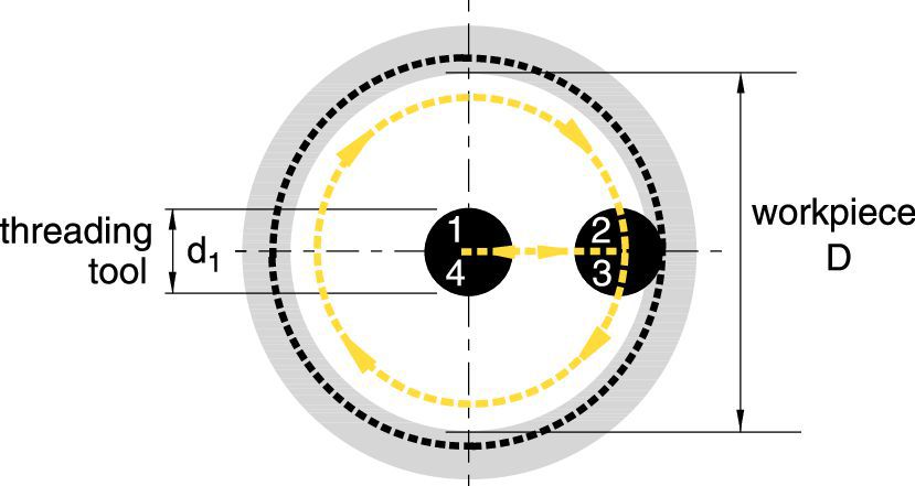
| 1–2: | radial entry |
| 2–3: | helical movement during one full orbit (360°) |
| 3–4: | radial exit |
| P1 = F1 + | (F1 x d1) | 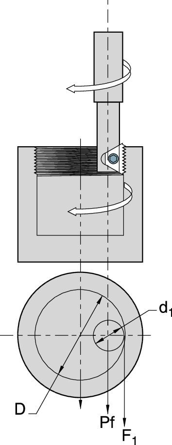 |  |
| D | external thread | internal thread | |
| P1 = program feed rate (in/min) D= major diameter (external thread) D= minor diameter (internal thread) d1 = cutting diameter, over insert | tool workpiece | ||
| F1 = fz x Z x n | RPM = | 12 x SFM | |
| π x d 1 | |||
| F1 =tool feed rate at the cutting edge (in/min) fz=inch per tooth (feed rate) Z=number of effective inserts in cutter n=rotational speed (spindle RPM) | SFM=cutting speed, surface feet per minute d1 =cutter diameter, over insert π=3.1416 | ||
 |  |
| internal thread | external thread |
| pitch (TPI) | 24 | 20 | 16 | 12 |
| pitch mm | 1,0 | 1,25 | 1,5 | 2,0 |
| cutter dia. d1 | minimum bore diameter D | |||
| .67 | .748 | .772 | .787 | .827 |
| .75 | .827 | .850 | .866 | .906 |
| .79 | .866 | .890 | .906 | .945 |
| insert IC | a (mm) | pitch (TPI) | internal thread | b | number of teeth | grade | external thread | b | number of teeth | grade | cutter type | ||
| catalog number | KC610M | KC620M | catalog number | KC610M | KC620M | ||||||||
| 32 | STN16 32UN-I | 14,99 | 19 | STN16 32UN-E | 14,99 | 19 | |||||||
| 28 | STN16 28UN-I | 14,48 | 16 | STN16 28UN-E | 14,48 | 16 | |||||||
| 27 | STN16 27UN-I | 14,22 | 15 | STN16 27UN-E | 14,22 | 15 | |||||||
| 24 | STN16 24UN-I | 13,97 | 14 | STN16 24UN-E | 14,73 | 14 | |||||||
| 9,53 | 16 | 20 | STN16 20UN-I | 13,97 | 11 | STN16 20UN-E | 13,97 | 11 | STN16 | ||||
| 18 | STN16 18UN-I | 14,22 | 10 | STN16 18UN-E | 14,22 | 10 | |||||||
| 16 | STN16 16UN-I | 14,22 | 9 | STN16 16UN-E | 14,22 | 9 | |||||||
| 14 | STN16 14UN-I | 14,48 | 8 | STN16 14UN-E | 14,48 | 8 | |||||||
| 13 | STN16 13UN-I | 13,72 | 7 | STN16 13UN-E | 13,72 | 7 | |||||||
| 12 | STN16 12UN-I | 14,73 | 7 | STN16 12UN-E | 14,73 | 7 | |||||||
| pitch (TPI) | 24 | 20 | 16 | 12 |
| pitch mm | 1,0 | 1,25 | 1,5 | 2,0 |
| cutter dia. d1 | minimum bore diameter D | |||
| 17,02 | 19,00 | 19,61 | 19,99 | 21,01 |
| 19,05 | 21,01 | 21,59 | 22,00 | 23,01 |
| 20,07 | 22,00 | 22,61 | 23,01 | 24,00 |
| insert IC | a inch (mm) | pitch (TPI) | internal thread | b | number of teeth | grade | external thread | b | number of teeth | grade | cutter type | ||
| catalog number | KC610M | KC620M | catalog number | KC610M | KC620M | ||||||||
| 32 | STN16 32UN-I | .59 | 19 | STN16 32UN-E | .59 | 19 | |||||||
| 28 | STN16 28UN-I | .57 | 16 | STN16 28UN-E | .57 | 16 | |||||||
| 27 | STN16 27UN-I | .56 | 15 | STN16 27UN-E | .56 | 15 | |||||||
| 24 | STN16 24UN-I | .55 | 14 | STN16 24UN-E | .58 | 14 | |||||||
| 3/8 | .63 (16) | 20 | STN16 20UN-I | .55 | 11 | STN16 20UN-E | .55 | 11 | STN16 | ||||
| 18 | STN16 18UN-I | .56 | 10 | STN16 18UN-E | .56 | 10 | |||||||
| 16 | STN16 16UN-I | .56 | 9 | STN16 16UN-E | .56 | 9 | |||||||
| 14 | STN16 14UN-I | .57 | 8 | STN16 14UN-E | .57 | 8 | |||||||
| 13 | STN16 13UN-I | .54 | 7 | STN16 13UN-E | .54 | 7 | |||||||
| 12 | STN16 12UN-I | .58 | 7 | STN16 12UN-E | .58 | 7 | |||||||
| Calculate the feed rates: | |||||
| First, find the RPM. | |||||
| RPM = | 12 x SFM | = | 12 x 500 | = | 2418 RPM |
| π x d1 | 3.14 x .79 | ||||
| Next, calculate the feed rate at the insert cutting edge (F1): | |||||
| (using the chosen feed per tooth of .004.) | |||||
| F1 = | IPT x nt x RPM | = | .004 X 1 X 2418 | = | 9.67 in/min |
| Finally, calculate the feed rate at the cutter centerline (F2): | |||||
| F2 = | F1 x (D - d1) | = | 9.67 x (1.182 - .79) | = | 3.207 in/min |
| D | 1.182 | ||||
| Select the thread milling method. | |||||
| Climb milling (preferred) see page . | |||||
| Calculate the radius of the tangential arc Re: | |||||
| Re = | (Ri - CL)2 + R02 | = | (.591 - .02)2 + .6252 | ||
| 2Ro | 2 x .625 | ||||
| Re = | .573333 in. | ||||
| Calculate the angle (β): | |||||
| β = | 90° + arc sin | Ro - Re | |||
| Re | |||||
| β = | 90° + arc sin | .625 - .573333 | |||
| .57333 | |||||
| β = | 90° + 5.17° | = | 95.17° | = | 95° 10' |
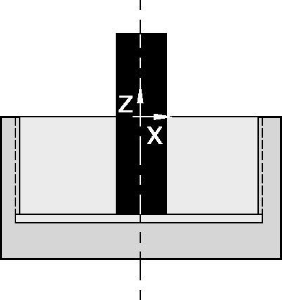
| Calculate the movement along the Z-axis during the entry approach from point “A” to point “B” (Zα). | |||||
| Zα= P (in) x | α° | = | .0625 | = | .0156 in, because α = 90° |
| 360° | 4 | ||||
| Calculate the “X” and “Y” values at the start of the entry approach. | |||||
| X = 0Y = -Ri + CL = -.591 + .02 = - .571 in. | |||||
| Define Z-axis location at the start of the entry approach. (NOTE: L = length of thread) | |||||
| Z = - (L + Zα) = - (.50 + .0156) = - .5156 in. | |||||
| Define the starting point. | |||||
| Xa = 0 | |||||
| Ya = 0 | |||||
| Calculate the feed rates: | |||||
| First, find the RPM. | |||||
| RPM = | 1000 x Vc | = | 1000 x 150 | = | 2387 RPM |
| π x d1 | π x 20 | ||||
| Next, calculate the feed rate at the insert cutting edge (F1): | |||||
| (using the chosen feed per tooth of 0,1mm.) | |||||
| F1 = | Fz x Z x N | = | 0,1 X 1 X 2387 | = | 238,7 mm/min |
| Finally, calculate the feed rate at the cutter centerline (F2): | |||||
| F2 = | F1 x (D - d1) | = | 238,7 x (30 | = | 79,57 mm/min |
| D | 30 | ||||
| Select the thread milling method. | |||||
| Climb milling (preferred) see page . | |||||
| Calculate the radius of the tangential arc Re: | |||||
| Re = | (Ri - CL)2 + RO2 | = | (15 | ||
| 2 x RO | 2 x 15,875 | ||||
| Re = | 14,55mm | ||||
| Calculate the angle (β): | |||||
| β = | 90° + arc sin | Ro - Re | |||
| Re | |||||
| β = | 90° + arc sin | 15,875 - 14,55 | |||
| 14,55 | |||||
| β = | 90° + 5.17° | = | 95,2° | = | 95° 12' |
| Calculate the movement along the Z-axis during the entry approach from point “A” to point “B” (Zα). | |||||
| Zα= P (mm) x | α° | = | 1,578 | = | 0,394mm because α = 90° |
| 360° | 4 | ||||
| Calculate the “X” and “Y” values at the start of the entry approach. | |||||
| X = 0Y = Ri + CL = 15 + 0,5 = 15,5mm | |||||
| Define Z-axis location at the start of the entry approach. (NOTE: L = length of thread) | |||||
| Z = (L + Zα) = 12,7 + 0,3945 = 13,0945mm | |||||
| Define the starting point. | |||||
| Xa = 0 | |||||
| Ya = 0 | |||||
| CNC Program (Fanuc 11M) | |||
| % | |||
| N10G90G00G57X0.000Y0.000 | |||
| N20G43H10Z0.M3S2417 | |||
| N30G91G00X0.Y0.Z–0.5156 | |||
| N40G41D60X0.000Y–0.5710Z0. | |||
| N50G03X0.6250Y0.5710Z0.0156R0.5733F3.206 | |||
| N60G03X0.Y0.Z0.0625I–0.625J0. | |||
| N70G03X–0.625Y0.5710Z0.0156R0.5733 | |||
| N80G00G40X0.Y–0.5710Z0. | |||
| N90G49G57G00Z8.0M5 | |||
| N100M30 | |||
| % | |||
| Ri = | D | Ro= | Do |
| 2 | 2 | ||
| D = minor diameter | Do = nominal diameter | ||
| α 90° | |||
 | |||
 | |||
| Appendix A | |
| Derivation of Formulas for Internal Thread Milling | |
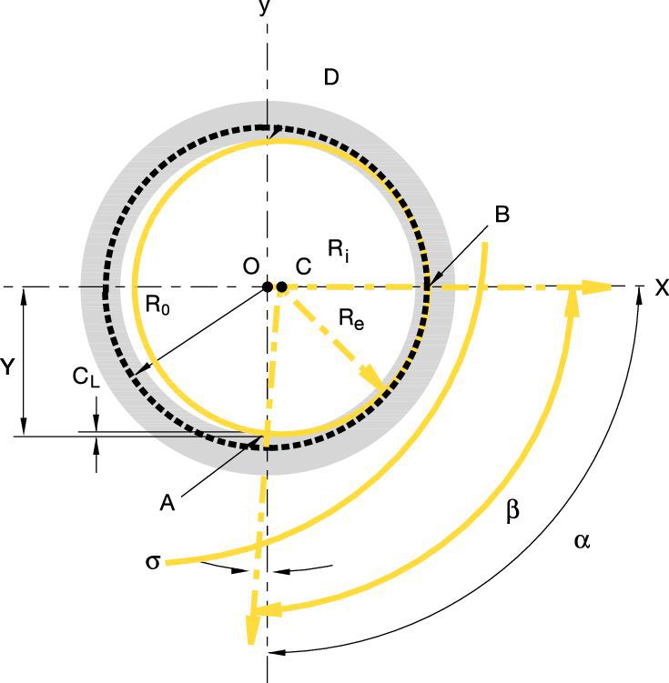
| Re, β, and X can be found by a geometric analysis of the entry path. | |
| This entry path is defined by the tool traveling along a circular path, with a radius of Re about the point C. | |
| R e = | (R i - C L) 2 + R o2 |
| 2R o | |
| Triangle OAC enables us to simply solve for Re. | |
| OA = Ri – CL CA = Re OC = Ro – Re | |
| Pythagoras’ law states: OA2 + OC2 = AC2 | |
| Replacing actual values, we get: | |
| (R i - C L) 2 + (R o - R e) 2 = R e2 | |
| Simplifying, we get: | |
| R e = | (R i - C L) 2 + R o2 |
| 2R 0 | |
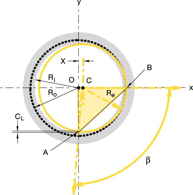 | |
| Find the angle β. | |||
| β can be easily found using the same triangle: | |||
| sin β = | AO | = | (Ro + CL) |
| AC | Re | ||
| β = arc sin | ( | Ro + CL | ) |
| Re | |||
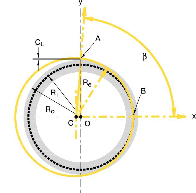 | |||
| Appendix B | |
| Derivation of Formulas for External Thread Milling | |
| Re, β, and X can be found by a geometric analysis of the entry path. | |
| This entry path is defined by the tool traveling along a circular path, with a radius of Re about the point C. | |
| R e = | (R o - C L) 2 + R i2 |
| 2R i | |
| Triangle OAC enables us to simply solve for Re. | |
| OA = Ro – CL CA = Re OC = Re – Ri | |
| Pythagoras’ law states: OA2 + OC2 = AC2 | |
| Replacing actual values, we get: | |
| (R o - C L) 2 + (R e - R i) 2 = R e2 | |
| Simplifying, we get: | |
| R e = | (R o - C L) 2 + R i2 |
| 2R i | |
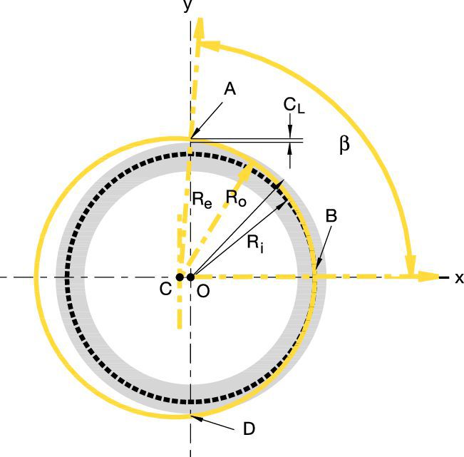 | |
| Find the angle β. | ||||
 | ||||
| sin |  | |||
 | = arc sin | ( | Ro - Re | ) |
| Re | ||||
| Therefore, β = 90° + arc sin | ( | Ro - Re | ) | |
| Re | ||||
 | ||||
| problem | possible cause | solution | |
| excessive insert flank wear |  | • Cutting speed too high. | • Reduce cutting speed. |
| • Chip is too thin. | • Increase feed rate. | ||
| • Insufficient coolant. | • Increase coolant quantity/pressure. | ||
| chipping of cutting edge |  | • Chip is too thick. | • Reduce feed rate. • Use the tangential arc method of entrance. • Increase RPM. |
| • Vibration. | • Check rigidity. | ||
| material build-up on the cutting edge |  | • Cutting speed too slow. | • Increase cutting speed. |
| • Chip thickness too small. | • Increase feed rate. | ||
| chatter/vibration | • Feed rate is too high. | • Reduce the feed. | |
| • Profile is too deep | • Execute two passes, each with increased cutting depth. • Execute two passes, each cutting only half the thread length. | ||
| • Thread length is too long. | • Execute two passes, each cutting only half of the thread length. | ||
| insufficient thread accuracy | • Tool deflection. | • Reduce feed rate. • Execute a zero cut. | |
| thread designation | standard designation | tolerance class |
| UN | ANSI B 1.174 | 2A/2B |
| UNJ | MIL-S-8879A | 3A/3B |
| ISO | R262 (DIN 13) | 6g/6H |
| NPT | USAS B2.1 : 1968 | standard NPT |
| NPTF | ANSI B 1.20.3-1976 | standard |
| BSW | B.S. 84 : 1956, DIN 259, ISO 228/1 : 1982 | medium class A |
| BSPT | B.S. 21 : 1985 | standard BSPT |
| ACME | ANSI B1/5 : 1988 | 3G |
| PG | DIN 40430 | standard |
| TR | DIN 103 | 7e/7H |
I have read and accepted the Terms & Conditions of use


ISO Catalog Number
ANSI Catalog Number
to find similar products.Please select a file to download
Models
Product data
. Please enter the desired qty for the material(s) you want to include in your promotion or Proceed Without Promotion and only your base materials will be added to the cart.
Minimum quantity should be
| SAP Material Number | ISO Catalog Number | Grade |
|---|
You are about to leave the Solution building process.
Are you sure you want to leave?