Product Similar To :
KCRA - RN • Face Mills • Inch
Face Mills
Material Number5703936
ISO Catalog IDKCRA200RN4304S075L175ANSI Catalog IDKCRA200RN4304S075L175
- P Steel
- S High-Temp Alloys
- .caption
Milling - Pressurized Air Coolant
Face Milling
Side Milling/Shoulder Milling: Ball Nose
Milling - Side and Face
Sending to {{cadTool}} in progress...
Downloaded file will be available after import in the {{cadTool}} tool library.
- Overview
- Application Data
- Downloads
- Compatible Parts Machine Side
- Compatible Parts Workpiece Side
- Spare Parts
- Reviews
- Q&A
| Material Number | 5703936 |
| ISO Catalog ID | KCRA200RN4304S075L175 |
| ANSI Catalog ID | KCRA200RN4304S075L175 |
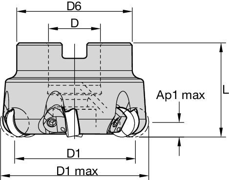
| [D1MAX] Maximum Cutting Diameter | 50.8 mm |
| [D1MAX] Maximum Cutting Diameter | 2 in |
| [D1] Effective Cutting Diameter | 38.1 mm |
| [D1] Effective Cutting Diameter | 1.5 in |
| [D] Adapter / Shank / Bore Diameter | 19.05 mm |
| [D] Adapter / Shank / Bore Diameter | 0.75 in |
| [D6] Hub Diameter | 42 mm |
| [D6] Hub Diameter | 1.6535 in |
| [L] Overall Length | 44.45 mm |
| [L] Overall Length | 1.75 in |
| [AP1MAX] 1st Maximum Cutting Depth | 6.35 mm |
| [AP1MAX] 1st Maximum Cutting Depth | 0.25 in |
| Number of Inserts | 4 |
| Max RPM | 23400 |
| Weight Pounds | 0.97 |
| Gage Insert | RNGN120400 |
Workpiece Materials
- Steel
- High-Temp Alloys
- .caption
Uses and application
Milling - Pressurized Air Coolant
Face Milling
Side Milling/Shoulder Milling: Ball Nose
Milling - Side and Face
Features and benefits
- First choice for face and shoulder milling high-temperature alloys.
- Higher material removal rate due to fine pitch cutters.
- Secure clamping system, improving process stability and reliability.
- Effective air coolant feature. Better chip flow and increased insert tool life.
Create Solution to calculate Feeds and Speeds
After creating a solution just choose the Feeds & Speeds icon and our system will provide recommendations. You can customize the information by adding your machine and specifications or make adjustments using the sliders.
Feeds
| Insert Geometry | Recommended Starting Feed per Tooth (Fz) in Relation to % of Radial Engagement (ae) | Insert Geometry | ||||||||||||||
| 10% | 20% | 30% | 40% | 50–100% | ||||||||||||
| .EGN | .003 | .004 | .005 | .003 | .003 | .003 | .002 | .002 | .003 | .002 | .002 | .003 | .002 | .002 | .003 | .EGN |
| .TGN | .005 | .007 | .008 | .004 | .005 | .006 | .003 | .004 | .005 | .003 | .004 | .005 | .003 | .004 | .005 | .TGN |
| Light | General | Heavy |
| Insert Geometry | Recommended Starting Feed per Tooth (Fz) in Relation to % of Radial Engagement (ae) | Insert Geometry | ||||||||||||||
| 10% | 20% | 30% | 40% | 50–100% | ||||||||||||
| .EGN | .004 | .004 | .005 | .003 | .003 | .004 | .003 | .003 | .003 | .002 | .003 | .003 | .002 | .003 | .003 | .EGN |
| .TGN | .006 | .008 | .009 | .004 | .006 | .007 | .004 | .005 | .006 | .004 | .005 | .005 | .003 | .005 | .005 | .TGN |
| Insert Geometry | Recommended Starting Feed per Tooth (Fz) in Relation to % of Radial Engagement (ae) | Insert Geometry | ||||||||||||||
| 10% | 20% | 30% | 40% | 50–100% | ||||||||||||
| .EGN | .007 | .008 | .009 | .005 | .006 | .007 | .005 | .005 | .006 | .004 | .005 | .006 | .004 | .005 | .006 | .EGN |
| .TGN | .010 | .014 | .016 | .008 | .010 | .012 | .007 | .009 | .010 | .006 | .008 | .010 | .006 | .008 | .010 | .TGN |
| Insert Geometry | Recommended Starting Feed per Tooth (Fz) in Relation to % of Radial Engagement (ae) | Insert Geometry | ||||||||||||||
| 10% | 20% | 30% | 40% | 50–100% | ||||||||||||
| .EGN | .005 | .006 | .007 | .004 | .004 | .005 | .003 | .004 | .004 | .003 | .003 | .004 | .003 | .003 | .004 | .EGN |
| .TGN | .008 | .010 | .012 | .006 | .008 | .009 | .005 | .007 | .008 | .005 | .006 | .007 | .005 | .006 | .007 | .TGN |
Speeds
Recommended Starting Speeds [SFM]
| Material Group | KYS30 | KYSP30 | |||||
| P | 1 | – | – | – | – | – | – |
| 2 | – | – | – | – | – | – | |
| 3 | – | – | – | – | – | – | |
| 4 | – | – | – | – | – | – | |
| 5 | – | – | – | – | – | – | |
| 6 | – | – | – | – | – | – | |
| M | 1 | – | – | – | – | – | – |
| 2 | – | – | – | – | – | – | |
| 3 | – | – | – | – | – | – | |
| K | 1 | – | – | – | – | – | – |
| 2 | – | – | – | – | – | – | |
| 3 | – | – | – | – | – | – | |
| N | 1 | – | – | – | – | – | – |
| 2 | – | – | – | – | – | – | |
| S | 1 | 2640 | 2160 | 1680 | 2640 | 2160 | 1680 |
| 2 | 2640 | 2160 | 1680 | 2640 | 2160 | 1680 | |
| 3 | 3840 | 3120 | 2400 | 3840 | 3120 | 2400 | |
| 4 | – | – | – | – | – | – | |
| H | 1 | – | – | – | – | – | – |
| 2 | – | – | – | – | – | – | |
| 3 | – | – | – | – | – | – | |
Insert Selection
| Material Group | Light | General | Heavy | |||
| – | (Light geometry) | – | (Strong geometry) | |||
| – | wear |  | toughness | |||
| – | Geometry | Grade | Geometry | Grade | Geometry | Grade |
| P1–P2 | – | – | – | – | – | – |
| P3–P4 | – | – | – | – | – | – |
| P5–P6 | – | – | – | – | – | – |
| M1–M2 | – | – | – | – | – | – |
| M3 | – | – | – | – | – | – |
| K1–K2 | – | – | – | – | – | – |
| K3 | – | – | – | – | – | – |
| N1–N2 | – | – | – | – | – | – |
| N3 | – | – | – | – | – | – |
| S1–S2 | .EGN | KYS30 | .EGN | KYS30 | .TGN | KYS30 |
| S3 | .EGN | KYSP30 | .EGN | KYSP30 | .TGN | KYSP30 |
| S4 | – | – | – | – | – | – |
| H1 | – | – | – | – | – | – |
TechnicalInfo
Insert Assembly Guide
| Safety Notes | |||||
 |  |  |  |  |  |
| Read all instructions carefully | Wear eye protection | Inspect and tighten fasteners regularly | Warning: Cutting hazard | Warning: Hot surfaces | Do not exceed maximum RPM |
| Assembly Instructions | |
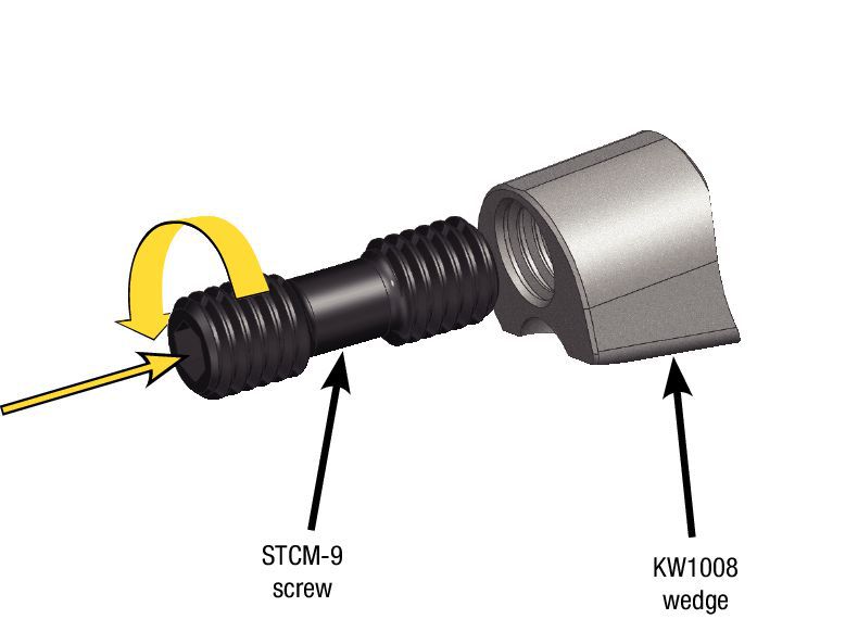
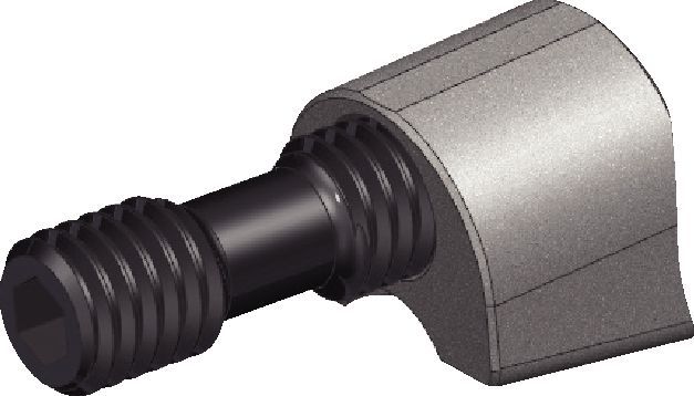
| Assemble STCM-25 screw to KW1008 wedge, 1 to 1 1/2 turns. | Wedge/screw assembly. |
 |  |
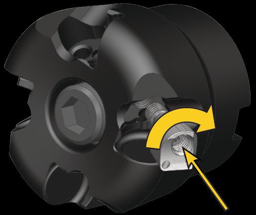
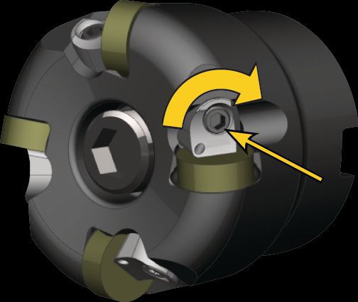
| Install wedge/screw assembly into cutter body, but maintain assembly gap for installing insert. | Slide insert, RNGN12... into pocket and torque wedge/insert assembly to 3,5 Nm (31 in/lbs). Repeat for each pocket. |
 |  |
I have read and accepted the Terms & Conditions of use

