FBX Drill
Modular Drill for Flat Bottom Holes


The FBX Drill is ideal for pre-machining of high-temperature alloy airframe structural parts.
4 large chip flutes, and 4 effective cutting edges on the outer diameter of the tool guarantee fast stock removal on large metal plates or forgings.
A center insert with 2 effective cutting edges and chip splitters enables perfect chip formation, allowing maximum feed rates.
The flat bottom drill point design eliminates radial forces. Ideal for applications on machines with lower horsepower.
The Bolt Taper Flange (BTF) connection provides maximum tool stiffness.
Nearly as rigid as a monoblock tool design but offers multiple machine side connections.

95mm length FBX Drill Bodies – Dia. 60mm, 75mm, 90mm
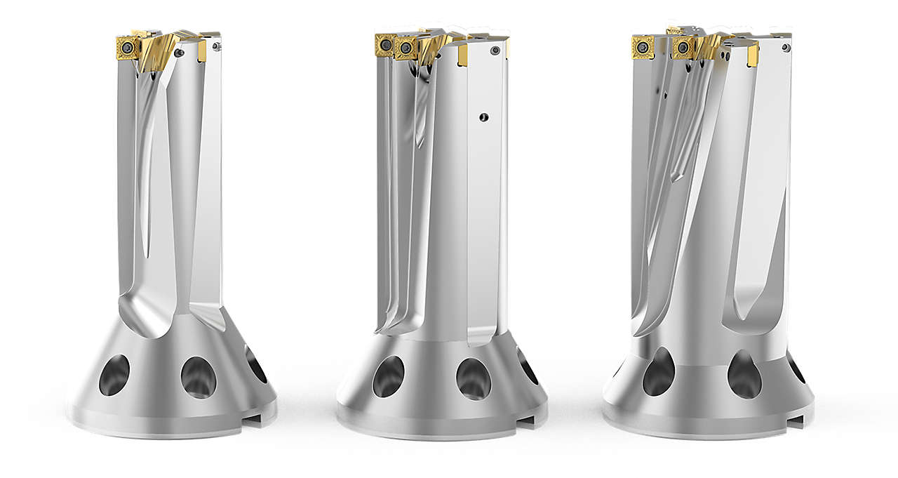
150mm length FBX Drill Bodies – Dia. 60mm, 75mm, 90mm
Flat bottom drill point design. Plunging holes with highest productivity through 4 effective cutting edges on the outer diameter.
Indexable inserts with 4 cutting edges provide low cost per cutting edge.
Adjustable coolant nozzles for efficient heat management.
Center insert with 2 effective cutting edges, with chip splitters for maximum feed.
4 chip flutes for hassle free chip evacuation, and maximum stability for chain hole drilling applications.
The Bolt Taper Flange (BTF) connection provides maximum tool stiffness.
Nearly as rigid as a monoblock tool design but offers multiple machine side connections.
The bolt taper flange tools provide maximum flexibility with standard KM4X, HSK, DV, CV and BT connection styles.
Raw Titanium Plate
Opening Cavities
(FBX Modular Drill for Flat Bottom Holes)
Roughing
Finishing
(Solid End Mills)
 Chain Drilling
(6)
Chain Drilling
(6)
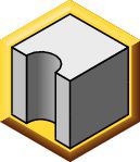
 Convex Drilling
(6)
Convex Drilling
(6)
 Corner Drilling 45°
(6)
Corner Drilling 45°
(6)
 Cross Hole Drilling
(6)
Cross Hole Drilling
(6)
 Drilling
(6)
Drilling
(6)
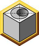
 Flat Bottom Drilling
(6)
Flat Bottom Drilling
(6)
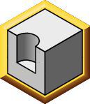
 Half Cylindrical Drilling
(6)
Half Cylindrical Drilling
(6)
 Inclined Entry Drilling
(6)
Inclined Entry Drilling
(6)
 Inclined Exit Drilling
(6)
Inclined Exit Drilling
(6)
 X-Offset Drilling
(6)
X-Offset Drilling
(6)
ISO Catalog Number
ANSI Catalog Number
to find similar products.Please select a file to download
Models
. Please enter the desired qty for the material(s) you want to include in your promotion or Proceed Without Promotion and only your base materials will be added to the cart.
Minimum quantity should be
| SAP Material Number | ISO Catalog Number | Grade |
|---|
Thank you for your registration, pending approval & completion of the registration, your access is currently limited. Full utilization of product search capabilities & collaboration space is available and will remain. Please allow 2 business days for registration completion.
Thank you for your successful registration. You now have immediate access to log in and utilize the site.
You are about to leave the Solution building process.
Are you sure you want to leave?


