Excellent surface quality and higher metal removal rates

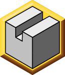
The unique design allows to apply the tool in multiple passes, called “step down”.

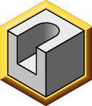
Most tools leave tool marks with every pass they take, resulting in unsatisfactory or low-quality wall finishes. This usually requires another finishing pass at the very end of the process.

Mill 4-15 eliminates that finishing pass with an additional tool, saving time and money.

Part of the First Choice Program.

Easy to select, easy to order, easy to apply, exceptional performance.

Learn More


Select Filters
Filters
View filters in
Metric
Inch
Key Filters
Workpiece Material
Workpiece Material
  • P Steel (138)
    • P0
      Low-Carbon Steels, Long Chipping C < .25%; <125 HB; <530 N/mm^2 UTS (133)
    • P1
      Low-Carbon Steels, Short Chipping C < .25%; <125 HB; <530 N/mm^2 UTS (133)
    • P2
      Medium and High Carbon Steels C < .25%; <220 HB; <25 HRC; >530 N/mm^2 UTS (133)
    • P3
      Alloy Steels & Tool Steels C > .25%; <330 HB; <35 HRC; 600-850 N/mm^2 UTS (133)
    • P4
      Alloy Steels & Tool Steels C > .25%; 350-420 HB; 35-43 HRC; 850-1400 N/mm^2 UTS (133)
    • P5
      Ferritic, Martensitic, and PH Stainless Steels <330 HB; <35 HRC; 600-900 N/mm^2 UTS (138)
    • P6
      High Strength Ferritic, Martensitic, and PH Stainless Steels 350-450 HB; 35-43 HRC; 900-2400 N/mm^2 UTS (138)
  • M Stainless Steel (138)
    • M1
      Austenitic Stainless Steel 130-200 HB; <600 N/mm^2 UTS (138)
    • M2
      High Strength Austenitic Stainless and Cast Stainless Steels 150-230 HB; <25 HRC; >600 N/mm^2 UTS (138)
    • M3
      Duplex Stainless Steel 135-275 HB; <30 HRC; 500-1200 N/mm^2 UTS (138)
  • K Cast Iron (137)
    • K1
      Gray Cast Iron 120-290 HB; <32 HRC; 125-500 N/mm^2 UTS (137)
    • K2
      Low and Medium Strength CGI and Ductile Irons 130-260 HB; <28 HRC; <600 N/mm^2 UTS (137)
    • K3
      High Strength Ductile and Austempered Ductile Iron 180-350 HB; <43 HRC; >600 N/mm^2 UTS (137)
  • N Non-Ferrous Materials (74)
    • N1
      Wrought Aluminum (74)
    • N2
      Low-Silicon Aluminum Alloys and Magnesium Alloys Si <12.2% (74)
    • N3
      High-Silicon Aluminum Alloys Si >12.2% (74)
  • S High-Temp Alloys (131)
    • S1
      Iron-Based, Heat-Resistant Alloys 160-260 HB; 25-48 HRC; 500-1200 N/mm^2 UTS (118)
    • S2
      Cobalt-Based, Heat-Resistant Alloys 250-450 HB; 25-48 HRC; 1000-1450 N/mm^2 UTS (118)
    • S3
      Nickel-Based, Heat Resistant Alloys 160-450 HB; <48 HRC; 600-1700 N/mm^2 UTS (118)
    • S4
      Titanium and Titanium Alloys 300-400 HB; 33-43 HRC; 900-1600 N/mm^2 UTS (131)
  • H Hardened Materials (94)
    • H1
      Hardened Materials 44-48 HRC (94)
Select First Choice
  • BR (20)
  • CN (94)
  • DE (91)
  • GB (48)
  • IN (17)
  • SG (41)
  • US (89)
Applications
Applications
  • Face Milling Face Milling (72)
  • Shoulder Milling Shoulder Milling (72)
  • Shoulder Roughing Shoulder Roughing (72)
  • Shoulder Square End Shoulder Square End (72)
  • Slot Milling Slot Milling (10)
  • Slot Square End Slot Square End (10)
Cutting Diameter
Cutting Diameter
  • 0.984 in (4)
  • 1.0 in (5)
  • 1.25 in (5)
  • 1.26 in (7)
  • 1.379 in (1)
  • 1.5 in (6)
  • 1.575 in (7)
  • 1.969 in (3)
  • 2.0 in (3)
  • 2.48 in (3)
  • 2.5 in (3)
  • 3.0 in (4)
  • 3.15 in (3)
  • 3.938 in (3)
  • 4.0 in (3)
  • 4.921 in (3)
  • 5.0 in (3)
  • 6.0 in (3)
  • 6.299 in (3)
Cutting Diameter Min to Cutting Diameter Max
Cutting Diameter
Cutting Diameter
  • 25.0 mm (4)
  • 25.401 mm (5)
  • 31.75 mm (5)
  • 32.0 mm (7)
  • 35.0 mm (1)
  • 38.1 mm (6)
  • 40.0 mm (7)
  • 50.0 mm (3)
  • 50.801 mm (3)
  • 63.0 mm (3)
  • 63.5 mm (3)
  • 76.2 mm (4)
  • 80.0 mm (3)
  • 100.0 mm (3)
  • 101.601 mm (3)
  • 125.0 mm (3)
  • 127.0 mm (3)
  • 152.4 mm (3)
  • 160.0 mm (3)
Cutting Diameter Min to Cutting Diameter Max
Cutting Length
Cutting Length
  • 15.5 mm (72)
Cutting Length Min to Cutting Length Max
Cutting Length
Cutting Length
  • 0.61 in (72)
Cutting Length Min to Cutting Length Max
Reach
Reach
  • 1.25 in (1)
  • 1.26 in (2)
  • 1.574 in (2)
  • 1.575 in (16)
  • 1.693 in (2)
  • 1.75 in (10)
  • 1.929 in (2)
  • 1.969 in (12)
  • 1.97 in (1)
  • 2.0 in (4)
  • 2.25 in (8)
  • 2.38 in (6)
  • 2.48 in (6)
Reach Min to Reach Max
Reach
Reach
  • 31.75 mm (1)
  • 32.0 mm (2)
  • 39.975 mm (2)
  • 40.0 mm (16)
  • 43.0 mm (2)
  • 44.45 mm (10)
  • 49.0 mm (2)
  • 50.0 mm (12)
  • 50.026 mm (1)
  • 50.801 mm (4)
  • 57.151 mm (8)
  • 60.45 mm (6)
  • 63.0 mm (6)
Reach Min to Reach Max
Tool Cutting Edge Angle
  • 90.0 (72)
Tool Cutting Edge Angle Min to Tool Cutting Edge Angle Max
Connection Style
Connection Style
  • 2 Key & Cutter Retention Screw (2)
  • 2 Key & Socket Head Cap Screw (1)
  • A-Socket Head Cap Screw (28)
  • B-Cutter Retention Screw (6)
  • SHCS or RetScrw Or BoltCircle (3)
  • Screw-On Connection (8)
  • Straight-Cylindrical (14)
  • Weldon (10)
Number of Flutes
Number of Flutes
  • 10 (1)
  • 11 (2)
  • 12 (4)
  • 16 (1)
  • 2 (9)
  • 3 (12)
  • 4 (13)
  • 5 (9)
  • 6 (6)
  • 7 (6)
  • 8 (5)
  • 9 (4)
Internal Coolant Capability
Over All Length [L]
Over All Length [L]
  • 1.574 in (2)
  • 1.575 in (12)
  • 1.75 in (4)
  • 1.969 in (5)
  • 1.97 in (1)
  • 2.0 in (4)
  • 2.116 in (1)
  • 2.126 in (1)
  • 2.38 in (6)
  • 2.48 in (6)
  • 2.539 in (4)
  • 2.715 in (2)
  • 3.504 in (1)
  • 3.781 in (1)
  • 3.938 in (1)
  • 4.03 in (1)
  • 4.331 in (2)
  • 4.37 in (3)
  • 4.529 in (1)
  • 4.53 in (3)
  • 6.694 in (1)
  • 7.875 in (4)
  • 8.0 in (3)
  • 10.0 in (3)
Over All Length [L] Min to Over All Length [L] Max
Over All Length [L]
Over All Length [L]
  • 39.975 mm (2)
  • 40.0 mm (12)
  • 44.45 mm (4)
  • 50.0 mm (5)
  • 50.026 mm (1)
  • 50.801 mm (4)
  • 53.75 mm (1)
  • 54.0 mm (1)
  • 60.45 mm (6)
  • 63.0 mm (6)
  • 64.5 mm (4)
  • 68.95 mm (2)
  • 89.0 mm (1)
  • 96.0 mm (1)
  • 100.0 mm (1)
  • 102.351 mm (1)
  • 110.0 mm (2)
  • 111.0 mm (3)
  • 115.025 mm (1)
  • 115.051 mm (3)
  • 170.0 mm (1)
  • 200.0 mm (4)
  • 203.201 mm (3)
  • 254.0 mm (3)
Over All Length [L] Min to Over All Length [L] Max
Corner configuration
Corner Radius
Corner Radius
  • 0.016 in (91)
  • 0.031 in (104)
  • 0.047 in (94)
  • 0.063 in (87)
  • 0.064 in (78)
  • 0.079 in (80)
Corner Radius Min to Corner Radius Max
Corner Radius
Corner Radius
  • 0.4 mm (91)
  • 0.8 mm (104)
  • 1.201 mm (94)
  • 1.6 mm (87)
  • 1.625 mm (78)
  • 2.0 mm (80)
Corner Radius Min to Corner Radius Max
Application
Grade Of Cutting Tool
  • KC422M (74)
  • KC520M (83)
  • KC522M (83)
  • KC725M (86)
  • KCK15 (84)
  • KCK20B (83)
  • KCPK30 (85)
  • KCPM20 (79)
  • KCPM40 (84)
  • KCSM30 (76)
  • KCSM40 (77)
Hand Of Tool
Hand Of Tool
  • R (72)
Wiper Insert
Wiper Insert
  • N (102)
Front-End
Neck Diameter
Neck Diameter
  • 0.728 in (1)
  • 0.929 in (1)
  • 0.984 in (1)
  • 1.176 in (1)
  • 1.177 in (1)
  • 1.185 in (2)
  • 1.22 in (4)
  • 1.24 in (4)
Neck Diameter Min to Neck Diameter Max
Neck Diameter
Neck Diameter
  • 18.5 mm (1)
  • 23.6 mm (1)
  • 25.0 mm (1)
  • 29.875 mm (1)
  • 29.901 mm (1)
  • 30.1 mm (2)
  • 31.0 mm (4)
  • 31.5 mm (4)
Neck Diameter Min to Neck Diameter Max
Center Cutting
Center Cutting
Insert Geometry
Shape
Shape
  • X-RECTANGLE MILL 4 90 (102)
Cutting Edge Length
Cutting Edge Length
  • 16.151 mm (19)
  • 16.901 mm (30)
  • 16.925 mm (5)
  • 17.0 mm (48)
Cutting Edge Length Min to Cutting Edge Length Max
Cutting Edge Length
Cutting Edge Length
  • 0.636 in (19)
  • 0.665 in (30)
  • 0.666 in (5)
  • 0.669 in (48)
Cutting Edge Length Min to Cutting Edge Length Max
Chip Breaker CBMD
Chip Breaker CBMD
  • GE (82)
  • GEH (1)
  • GEM (19)
Cutting Tool Material
  • H W (102)
Tolerance Class
Tolerance Class
  • G (67)
  • P (35)
Back-End
Connection Type
Connection Type
  • CYLINDRICAL (24)
  • SCREW-ON (8)
  • SHELL MILL (40)
Back-End Diameter
Back-End Diameter
  • 12.701 mm (1)
  • 16.0 mm (2)
  • 19.05 mm (6)
  • 21.0 mm (2)
  • 22.0 mm (6)
  • 25.0 mm (3)
  • 25.401 mm (8)
  • 27.0 mm (3)
  • 29.0 mm (6)
  • 31.75 mm (8)
  • 32.0 mm (12)
  • 38.1 mm (6)
  • 40.0 mm (6)
  • 50.801 mm (3)
Back-End Diameter Min to Back-End Diameter Max
Back-End Diameter
Back-End Diameter
  • 0.5 in (1)
  • 0.63 in (2)
  • 0.75 in (6)
  • 0.828 in (2)
  • 0.866 in (6)
  • 0.984 in (3)
  • 1.0 in (8)
  • 1.063 in (3)
  • 1.143 in (6)
  • 1.25 in (8)
  • 1.26 in (12)
  • 1.5 in (6)
  • 1.575 in (6)
  • 2.0 in (3)
Back-End Diameter Min to Back-End Diameter Max
No filters matching ""
You are about to add to your My Solutions page. Do you want to proceed?
product-image
Please adjust the following properties from

ISO Catalog Number

ANSI Catalog Number

to find similar products.

The following files are available

Please select a file to download

Models

You should be logged to see your dashboard information
Session expired due to inactivity, please login again
The product/s () you were trying to add to the cart is/are not available, please contact customer service
item(s) successfully added to the cart
View Cart

. Please enter the desired qty for the material(s) you want to include in your promotion or Proceed Without Promotion and only your base materials will be added to the cart.

Minimum quantity should be

SAP Material Number ISO Catalog Number Grade    
Thank you for your registration, pending approval & completion of the registration, your access is currently limited. Full utilization of product search capabilities & collaboration space is available and will remain. Please allow 2 business days for registration completion.

You are about to leave the Solution building process.

Are you sure you want to leave?