Read More

Mill 4-11™ - 90° shoulder milling to the extreme

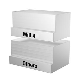
The Mill 4-11 Series is specially engineered to achieve excellent surface quality and higher metal removal rates in shoulder milling applications. Its unique design allows you to apply the tool in multiple passes (step down) with outstanding results. From roughing to finishing operations, the Mill 4-11 series is applicable in a wide range of workpiece materials: steel, cast iron, stainless steel, non-ferrous materials, and high-temp alloys.

  • Double-sided strong insert with 4 cutting edges.
  • High positive geometry for lower cutting forces.
  • Superior wall and surface finish capabilities.
  • Comprehensive offering to cover all applications in all material groups.

第1選択プログラムの製品。

選択や注文、使用が容易で、並外れた性能。

詳細を見る

STEPLESS SOLUTIONS

A challenge with step down applications is that most tools leave tool marks with every pass they take, resulting in unsatisfactory or low quality wall finishes, which require another finishing pass at the very end of the process.

Applying Mill 4-11™ delivers pristine wall finishes, and eliminates that finishing pass with an additional tool. That saves you time and reduces your production cost.

フィルタを選択
フィルタ
フィルタ表示
メートル
インチ
keyFilters
Workpiece Material
Workpiece Material
  • P Steel (103)
    • P0
      Low-Carbon Steels, Long Chipping C < .25%; <125 HB; <530 N/mm^2 UTS (98)
    • P1
      Low-Carbon Steels, Short Chipping C < .25%; <125 HB; <530 N/mm^2 UTS (98)
    • P2
      Medium and High Carbon Steels C < .25%; <220 HB; <25 HRC; >530 N/mm^2 UTS (98)
    • P3
      Alloy Steels & Tool Steels C > .25%; <330 HB; <35 HRC; 600-850 N/mm^2 UTS (98)
    • P4
      Alloy Steels & Tool Steels C > .25%; 350-420 HB; 35-43 HRC; 850-1400 N/mm^2 UTS (98)
    • P5
      Ferritic, Martensitic, and PH Stainless Steels <330 HB; <35 HRC; 600-900 N/mm^2 UTS (103)
    • P6
      High Strength Ferritic, Martensitic, and PH Stainless Steels 350-450 HB; 35-43 HRC; 900-2400 N/mm^2 UTS (103)
  • M Stainless Steel (103)
    • M1
      Austenitic Stainless Steel 130-200 HB; <600 N/mm^2 UTS (103)
    • M2
      High Strength Austenitic Stainless and Cast Stainless Steels 150-230 HB; <25 HRC; >600 N/mm^2 UTS (103)
    • M3
      Duplex Stainless Steel 135-275 HB; <30 HRC; 500-1200 N/mm^2 UTS (103)
  • K Cast Iron (94)
    • K1
      Gray Cast Iron 120-290 HB; <32 HRC; 125-500 N/mm^2 UTS (94)
    • K2
      Low and Medium Strength CGI and Ductile Irons 130-260 HB; <28 HRC; <600 N/mm^2 UTS (94)
    • K3
      High Strength Ductile and Austempered Ductile Iron 180-350 HB; <43 HRC; >600 N/mm^2 UTS (94)
  • N Non-Ferrous Materials (65)
    • N1
      Wrought Aluminum (65)
    • N2
      Low-Silicon Aluminum Alloys and Magnesium Alloys Si <12.2% (65)
    • N3
      High-Silicon Aluminum Alloys Si >12.2% (65)
  • S High-Temp Alloys (102)
    • S1
      Iron-Based, Heat-Resistant Alloys 160-260 HB; 25-48 HRC; 500-1200 N/mm^2 UTS (96)
    • S2
      Cobalt-Based, Heat-Resistant Alloys 250-450 HB; 25-48 HRC; 1000-1450 N/mm^2 UTS (96)
    • S3
      Nickel-Based, Heat Resistant Alloys 160-450 HB; <48 HRC; 600-1700 N/mm^2 UTS (96)
    • S4
      Titanium and Titanium Alloys 300-400 HB; 33-43 HRC; 900-1600 N/mm^2 UTS (102)
  • H Hardened Materials (74)
    • H1
      Hardened Materials 44-48 HRC (74)
第1選択を選択
  • BR (17)
  • CN (74)
  • DE (73)
  • GB (45)
  • IN (11)
  • SG (27)
  • US (65)
Applications
Applications
  • Face Milling Face Milling (63)
  • Shoulder Bottom Shoulder Shoulder Bottom Shoulder (63)
  • Shoulder Milling Shoulder Milling (63)
  • Shoulder Roughing Shoulder Roughing (63)
  • Shoulder Square End Shoulder Square End (63)
  • Slot Milling Slot Milling (10)
  • Slot Side Slot Side (10)
  • Slot Square End Slot Square End (10)
Cutting Diameter
Cutting Diameter
  • 0.625 in (3)
  • 0.63 in (4)
  • 0.75 in (6)
  • 0.787 in (6)
  • 0.984 in (5)
  • 1.0 in (7)
  • 1.25 in (5)
  • 1.26 in (6)
  • 1.5 in (3)
  • 1.575 in (5)
  • 1.969 in (3)
  • 2.0 in (2)
  • 2.48 in (2)
  • 2.5 in (2)
  • 3.0 in (2)
  • 3.15 in (2)
Cutting Diameter Min to Cutting Diameter Max
Cutting Diameter
Cutting Diameter
  • 15.875 mm (3)
  • 16.0 mm (4)
  • 19.05 mm (6)
  • 20.0 mm (6)
  • 25.0 mm (5)
  • 25.401 mm (7)
  • 31.75 mm (5)
  • 32.0 mm (6)
  • 38.1 mm (3)
  • 40.0 mm (5)
  • 50.0 mm (3)
  • 50.801 mm (2)
  • 63.0 mm (2)
  • 63.5 mm (2)
  • 76.2 mm (2)
  • 80.0 mm (2)
Cutting Diameter Min to Cutting Diameter Max
Cutting Length
Cutting Length
  • 11.0 mm (63)
Cutting Length Min to Cutting Length Max
Cutting Length
Cutting Length
  • 0.433 in (63)
Cutting Length Min to Cutting Length Max
Reach
Reach
  • 0.984 in (4)
  • 1.0 in (3)
  • 1.1 in (6)
  • 1.102 in (6)
  • 1.25 in (1)
  • 1.26 in (1)
  • 1.575 in (17)
  • 1.693 in (3)
  • 1.75 in (9)
  • 1.929 in (6)
  • 1.969 in (2)
  • 2.25 in (5)
Reach Min to Reach Max
Reach
Reach
  • 25.0 mm (4)
  • 25.401 mm (3)
  • 27.951 mm (6)
  • 28.0 mm (6)
  • 31.75 mm (1)
  • 32.0 mm (1)
  • 40.0 mm (17)
  • 43.0 mm (3)
  • 44.45 mm (9)
  • 49.0 mm (6)
  • 50.0 mm (2)
  • 57.151 mm (5)
Reach Min to Reach Max
Tool Cutting Edge Angle
  • 90.0 (63)
Tool Cutting Edge Angle Min to Tool Cutting Edge Angle Max
Connection Style
Connection Style
  • A-Socket Head Cap Screw (18)
  • Screw-On Connection (8)
  • Straight-Cylindrical (24)
  • Weldon (13)
Number of Flutes
Number of Flutes
  • 10 (1)
  • 2 (11)
  • 3 (13)
  • 4 (12)
  • 5 (12)
  • 6 (4)
  • 7 (5)
  • 8 (3)
  • 9 (2)
Internal Coolant Capability
Over All Length [L]
Over All Length [L]
  • 1.575 in (14)
  • 1.681 in (1)
  • 1.75 in (2)
  • 1.889 in (1)
  • 1.891 in (1)
  • 1.969 in (2)
  • 2.116 in (1)
  • 2.441 in (1)
  • 2.539 in (2)
  • 2.715 in (1)
  • 2.906 in (1)
  • 2.914 in (1)
  • 3.11 in (2)
  • 3.13 in (2)
  • 3.504 in (1)
  • 3.543 in (2)
  • 3.781 in (1)
  • 3.938 in (1)
  • 4.0 in (2)
  • 4.03 in (1)
  • 4.331 in (3)
  • 4.5 in (2)
  • 4.53 in (2)
  • 5.0 in (2)
  • 5.906 in (3)
  • 6.0 in (3)
  • 6.694 in (2)
  • 7.0 in (2)
  • 7.875 in (3)
  • 8.0 in (1)
Over All Length [L] Min to Over All Length [L] Max
Over All Length [L]
Over All Length [L]
  • 40.0 mm (14)
  • 42.7 mm (1)
  • 44.45 mm (2)
  • 47.95 mm (1)
  • 48.0 mm (1)
  • 50.0 mm (2)
  • 53.75 mm (1)
  • 62.0 mm (1)
  • 64.5 mm (2)
  • 68.95 mm (1)
  • 73.8 mm (1)
  • 74.0 mm (1)
  • 79.0 mm (2)
  • 79.5 mm (2)
  • 89.0 mm (1)
  • 90.0 mm (2)
  • 96.0 mm (1)
  • 100.0 mm (1)
  • 101.601 mm (2)
  • 102.351 mm (1)
  • 110.0 mm (3)
  • 114.301 mm (2)
  • 115.051 mm (2)
  • 127.0 mm (2)
  • 150.0 mm (3)
  • 152.4 mm (3)
  • 170.0 mm (2)
  • 177.8 mm (2)
  • 200.0 mm (3)
  • 203.201 mm (1)
Over All Length [L] Min to Over All Length [L] Max
cornerConfiguration
Corner Radius
Corner Radius
  • 0.016 in (70)
  • 0.031 in (91)
  • 0.047 in (76)
  • 0.063 in (72)
Corner Radius Min to Corner Radius Max
Corner Radius
Corner Radius
  • 0.4 mm (70)
  • 0.8 mm (91)
  • 1.201 mm (76)
  • 1.6 mm (72)
Corner Radius Min to Corner Radius Max
application
Grade Of Cutting Tool
  • KC422M (65)
  • KC520M (68)
  • KC522M (72)
  • KC725M (69)
  • KCK15 (69)
  • KCK20B (67)
  • KCPK30 (69)
  • KCPM20 (64)
  • KCPM40 (75)
  • KCSM30 (64)
  • KCSM40 (68)
Hand Of Tool
Hand Of Tool
  • R (63)
Wiper Insert
Wiper Insert
  • N (57)
frontEnd
Neck Diameter
Neck Diameter
  • 0.74 in (1)
  • 1.23 in (1)
  • 1.24 in (2)
Neck Diameter Min to Neck Diameter Max
Neck Diameter
Neck Diameter
  • 18.8 mm (1)
  • 31.25 mm (1)
  • 31.5 mm (2)
Neck Diameter Min to Neck Diameter Max
Center Cutting
Center Cutting
insertGeometry
Shape
Shape
  • X-RECTANGLE MILL 4 90 (57)
Cutting Edge Length
Cutting Edge Length
  • 12.101 mm (20)
  • 12.175 mm (37)
Cutting Edge Length Min to Cutting Edge Length Max
Cutting Edge Length
Cutting Edge Length
  • 0.477 in (20)
  • 0.48 in (37)
Cutting Edge Length Min to Cutting Edge Length Max
Chip Breaker CBMD
Chip Breaker CBMD
  • GE (40)
  • GEM (15)
  • LE (2)
Cutting Tool Material
  • H W (57)
Tolerance Class
Tolerance Class
  • G (37)
  • P (20)
backEnd
Connection Type
Connection Type
  • CYLINDRICAL (37)
  • SCREW-ON (8)
  • SHELL MILL (18)
Back-End Diameter
Back-End Diameter
  • 12.701 mm (2)
  • 13.0 mm (1)
  • 15.875 mm (3)
  • 16.0 mm (6)
  • 18.0 mm (2)
  • 19.0 mm (1)
  • 19.05 mm (9)
  • 20.0 mm (5)
  • 21.0 mm (2)
  • 22.0 mm (5)
  • 25.0 mm (4)
  • 25.401 mm (7)
  • 27.0 mm (2)
  • 29.0 mm (3)
  • 31.75 mm (5)
  • 32.0 mm (6)
Back-End Diameter Min to Back-End Diameter Max
Back-End Diameter
Back-End Diameter
  • 0.5 in (2)
  • 0.512 in (1)
  • 0.625 in (3)
  • 0.63 in (6)
  • 0.709 in (2)
  • 0.748 in (1)
  • 0.75 in (9)
  • 0.787 in (5)
  • 0.828 in (2)
  • 0.866 in (5)
  • 0.984 in (4)
  • 1.0 in (7)
  • 1.063 in (2)
  • 1.143 in (3)
  • 1.25 in (5)
  • 1.26 in (6)
Back-End Diameter Min to Back-End Diameter Max
No filters matching ""
マイソリューションページにを追加しようとしています. 続行しますか?
product-image
Please adjust the following properties from

ISO製品型番

ANSI製品型番

to find similar products.

The following files are available

Please select a file to download

Models

Product data

ダッシュボード情報を表示するには、ログインする必要があります
Session expired due to inactivity, please login again
カートに追加しようとした製品()はありません カスタマーサービスにお問い合わせください。
アイテムがカートに正常に追加されました
カートを表示

. Please enter the desired qty for the material(s) you want to include in your promotion or Proceed Without Promotion and only your base materials will be added to the cart.

Minimum quantity should be

SAP Material Number ISO製品型番 材種    

Thank you for your registration, pending approval & completion of the registration, your access is currently limited. Full utilization of product search capabilities & collaboration space is available and will remain. Please allow 2 business days for registration completion.

ご登録いただきありがとうございます。今からウェブサイトにアクセス頂き、ご利用が可能でございます。

You are about to leave the Solution building process.

Are you sure you want to leave?