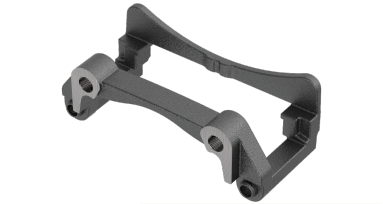
接線方向ショルダーミーリング

  • Mill 4-12KT は、所要動力が最大15%低いため、40テーパー機でもフィード量を高めることができます。
  • 三角形のマージンを特長とする専有のインサート設計により、鋼と鋳鉄のアプリケーションでこれまでにない安定性を実現します。
  • 軸方向の振れが最小限に抑えられるため、優れた床仕上げが可能です。
  • このプログラムでは、7種類の材種、7種類のコーナーR、最大0.472"(12 mm)の切込み量が取り揃えられることで汎用性を実現し、幅広いショルダーミーリングアプリケーションに対応します。
  • 左勝手インサートには、特注のスロットミル向けに複数のコーナーノーズRが用意されています。
  • ファインピッチカッターは、鋳鉄の粗加工や仕上げ加工の際に、径方向の切込み量(ae)が小さいため、高い生産性を実現します。
  • 強化されたHDブレーカー形状インサートで、重切削や断続切削での安定性が向上し、破損のリスクが低減されます。


Mill 4-12KT用の新しいPSTSインサート

  • 精密プレス加工によるPUブレーカー形状で、切れ刃あたりのコストを最少化
  • 強力な切れ刃で生産性と切り屑除去率を向上

著しい断続切削に容易に対処

Mill 4-12KTインサートの強力な切れ刃は、困難なアプリケーションや重切削、最も著しい断続にも対応できるように設計されました。スイスチーズを切った後でも、目に見える摩耗や欠損は生じませんでした。難易度の高いアプリケーションに対応しなければならない場合は、この接線方向ミーリングカッターが最適です。

動画を観て、ご自身でお確かめください。

MRRの向上と工具コストの削減 

課題:乾式粗加工から仕上げ加工までのアプリケーションでミーリング加工を行う際に、生産性を向上させることで、部品あたりのコスト(CPP)を改善します。

ソリューション:Mill 4-12KT

結果:工具寿命を損なうことなく、1刃あたりの切り屑厚さが増大することで、MRRが向上し、表面仕上げが改善されます。Mill 4-12KTは、切り屑厚さあたりのインサート数が少ないため、工具コストも削減され、再現性も向上しました。

すべての記事を読む
KMT_Innov20_IndexableMilling_006_007_EN_me.indd
フィルタを選択
フィルタ
フィルタ表示
メートル
インチ
keyFilters
Workpiece Material
Workpiece Material
  • P Steel (107)
    • P0
      Low-Carbon Steels, Long Chipping C < .25%; <125 HB; <530 N/mm^2 UTS (92)
    • P1
      Low-Carbon Steels, Short Chipping C < .25%; <125 HB; <530 N/mm^2 UTS (92)
    • P2
      Medium and High Carbon Steels C < .25%; <220 HB; <25 HRC; >530 N/mm^2 UTS (92)
    • P3
      Alloy Steels & Tool Steels C > .25%; <330 HB; <35 HRC; 600-850 N/mm^2 UTS (92)
    • P4
      Alloy Steels & Tool Steels C > .25%; 350-420 HB; 35-43 HRC; 850-1400 N/mm^2 UTS (92)
    • P5
      Ferritic, Martensitic, and PH Stainless Steels <330 HB; <35 HRC; 600-900 N/mm^2 UTS (107)
    • P6
      High Strength Ferritic, Martensitic, and PH Stainless Steels 350-450 HB; 35-43 HRC; 900-2400 N/mm^2 UTS (107)
  • M Stainless Steel (107)
    • M1
      Austenitic Stainless Steel 130-200 HB; <600 N/mm^2 UTS (107)
    • M2
      High Strength Austenitic Stainless and Cast Stainless Steels 150-230 HB; <25 HRC; >600 N/mm^2 UTS (107)
    • M3
      Duplex Stainless Steel 135-275 HB; <30 HRC; 500-1200 N/mm^2 UTS (107)
  • K Cast Iron (94)
    • K1
      Gray Cast Iron 120-290 HB; <32 HRC; 125-500 N/mm^2 UTS (94)
    • K2
      Low and Medium Strength CGI and Ductile Irons 130-260 HB; <28 HRC; <600 N/mm^2 UTS (94)
    • K3
      High Strength Ductile and Austempered Ductile Iron 180-350 HB; <43 HRC; >600 N/mm^2 UTS (94)
  • S High-Temp Alloys (107)
    • S1
      Iron-Based, Heat-Resistant Alloys 160-260 HB; 25-48 HRC; 500-1200 N/mm^2 UTS (92)
    • S2
      Cobalt-Based, Heat-Resistant Alloys 250-450 HB; 25-48 HRC; 1000-1450 N/mm^2 UTS (92)
    • S3
      Nickel-Based, Heat Resistant Alloys 160-450 HB; <48 HRC; 600-1700 N/mm^2 UTS (92)
    • S4
      Titanium and Titanium Alloys 300-400 HB; 33-43 HRC; 900-1600 N/mm^2 UTS (107)
  • H Hardened Materials (53)
    • H1
      Hardened Materials 44-48 HRC (53)
Applications
Applications
  • Face Milling Face Milling (41)
  • Shoulder Milling Shoulder Milling (41)
  • Shoulder Roughing Shoulder Roughing (28)
  • Shoulder Square End Shoulder Square End (13)
Cutting Diameter
Cutting Diameter
  • 1.969 in (3)
  • 2.0 in (3)
  • 2.48 in (4)
  • 2.5 in (3)
  • 3.0 in (3)
  • 3.15 in (3)
  • 3.938 in (3)
  • 4.0 in (3)
  • 4.921 in (3)
  • 5.0 in (3)
  • 6.0 in (3)
  • 6.299 in (3)
  • 7.875 in (2)
  • 8.0 in (2)
Cutting Diameter Min to Cutting Diameter Max
Cutting Diameter
Cutting Diameter
  • 50.0 mm (3)
  • 50.801 mm (3)
  • 63.0 mm (4)
  • 63.5 mm (3)
  • 76.2 mm (3)
  • 80.0 mm (3)
  • 100.0 mm (3)
  • 101.601 mm (3)
  • 125.0 mm (3)
  • 127.0 mm (3)
  • 152.4 mm (3)
  • 160.0 mm (3)
  • 200.0 mm (2)
  • 203.201 mm (2)
Cutting Diameter Min to Cutting Diameter Max
Cutting Length
Cutting Length
  • 12.125 mm (6)
  • 12.15 mm (35)
Cutting Length Min to Cutting Length Max
Cutting Length
Cutting Length
  • 0.478 in (6)
  • 0.479 in (35)
Cutting Length Min to Cutting Length Max
Reach
Reach
  • 1.5 in (3)
  • 1.575 in (7)
  • 1.75 in (6)
  • 1.969 in (6)
  • 2.0 in (3)
  • 2.375 in (8)
  • 2.48 in (8)
Reach Min to Reach Max
Reach
Reach
  • 38.1 mm (3)
  • 40.0 mm (7)
  • 44.45 mm (6)
  • 50.0 mm (6)
  • 50.801 mm (3)
  • 60.325 mm (8)
  • 63.0 mm (8)
Reach Min to Reach Max
Tool Cutting Edge Angle
  • 90.0 (41)
Tool Cutting Edge Angle Min to Tool Cutting Edge Angle Max
Connection Style
Connection Style
  • A-Socket Head Cap Screw (29)
  • B-Cutter Retention Screw (5)
  • C-Bolt Circle (7)
Number of Flutes
Number of Flutes
  • 10 (2)
  • 11 (4)
  • 12 (4)
  • 14 (2)
  • 16 (6)
  • 18 (2)
  • 22 (2)
  • 4 (2)
  • 5 (4)
  • 6 (4)
  • 7 (3)
  • 8 (4)
  • 9 (2)
Internal Coolant Capability
Over All Length [L]
Over All Length [L]
  • 1.5 in (3)
  • 1.575 in (7)
  • 1.75 in (6)
  • 1.969 in (6)
  • 2.0 in (3)
  • 2.375 in (8)
  • 2.48 in (8)
Over All Length [L] Min to Over All Length [L] Max
Over All Length [L]
Over All Length [L]
  • 38.1 mm (3)
  • 40.0 mm (7)
  • 44.45 mm (6)
  • 50.0 mm (6)
  • 50.801 mm (3)
  • 60.325 mm (8)
  • 63.0 mm (8)
Over All Length [L] Min to Over All Length [L] Max
cornerConfiguration
Corner Radius
Corner Radius
  • 0.016 in (49)
  • 0.031 in (68)
  • 0.047 in (53)
  • 0.061 in (61)
  • 0.078 in (54)
  • 0.094 in (47)
  • 0.125 in (47)
Corner Radius Min to Corner Radius Max
Corner Radius
Corner Radius
  • 0.4 mm (49)
  • 0.8 mm (68)
  • 1.201 mm (53)
  • 1.55 mm (61)
  • 1.975 mm (54)
  • 2.375 mm (47)
  • 3.176 mm (47)
Corner Radius Min to Corner Radius Max
application
Grade Of Cutting Tool
  • KC522M (53)
  • KC725M (48)
  • KCK15 (52)
  • KCK20 (43)
  • KCK20B (54)
  • KCPK30 (56)
  • KCPM40 (58)
  • KCSM40 (56)
  • X00626 (41)
Hand Of Tool
Hand Of Tool
  • R (41)
Wiper Insert
Wiper Insert
  • N (92)
Maximum Ramp Angle
Maximum Ramp Angle
  • 0.008 (4)
  • 0.01 (3)
  • 0.011 (3)
  • 0.013 (6)
  • 0.016 (6)
  • 0.02 (3)
  • 0.021 (3)
  • 0.026 (7)
  • 0.041 (3)
  • 0.042 (3)
Maximum Ramp Angle Min to Maximum Ramp Angle Max
frontEnd
Insert Shape
Insert Shape
  • L-RECTANGLE 90 (5)
  • L-RECTANGLE ON EDGE 90 (128)
Center Cutting
Center Cutting
insertGeometry
Shape
Shape
  • L-RECTANGLE 90 (5)
  • L-RECTANGLE ON EDGE 90 (87)
Chip Breaker CBMD
Chip Breaker CBMD
  • GE (74)
  • HD (12)
  • PU (6)
Cutting Tool Material
  • H W (92)
Tolerance Class
Tolerance Class
  • G (86)
  • P (6)
backEnd
Connection Type
Connection Type
  • SHELL MILL (41)
Back-End Diameter
Back-End Diameter
  • 19.05 mm (3)
  • 22.0 mm (7)
  • 25.401 mm (6)
  • 27.0 mm (3)
  • 31.75 mm (3)
  • 32.0 mm (3)
  • 38.1 mm (3)
  • 40.0 mm (6)
  • 50.801 mm (3)
  • 60.0 mm (2)
  • 63.5 mm (2)
Back-End Diameter Min to Back-End Diameter Max
Back-End Diameter
Back-End Diameter
  • 0.75 in (3)
  • 0.866 in (7)
  • 1.0 in (6)
  • 1.063 in (3)
  • 1.25 in (3)
  • 1.26 in (3)
  • 1.5 in (3)
  • 1.575 in (6)
  • 2.0 in (3)
  • 2.362 in (2)
  • 2.5 in (2)
Back-End Diameter Min to Back-End Diameter Max
No filters matching ""
マイソリューションページにを追加しようとしています. 続行しますか?
product-image
Please adjust the following properties from

ISO製品型番

ANSI製品型番

to find similar products.

The following files are available

Please select a file to download

Models

ダッシュボード情報を表示するには、ログインする必要があります
Session expired due to inactivity, please login again
カートに追加しようとした製品()はありません カスタマーサービスにお問い合わせください。
アイテムがカートに正常に追加されました
カートを表示

. Please enter the desired qty for the material(s) you want to include in your promotion or Proceed Without Promotion and only your base materials will be added to the cart.

Minimum quantity should be

SAP Material Number ISO製品型番 材種    

Thank you for your registration, pending approval & completion of the registration, your access is currently limited. Full utilization of product search capabilities & collaboration space is available and will remain. Please allow 2 business days for registration completion.

ご登録いただきありがとうございます。今からウェブサイトにアクセス頂き、ご利用が可能でございます。

You are about to leave the Solution building process.

Are you sure you want to leave?