List Price
/each
Discount
Your Price
/each
Sold in pkg. of 0Adjusted to meet the minimum package size.
Minimum qty: 0Adjusted to meet the minimum quantity requirement.
In StockThis item is no longer availableLonger Delivery


Downloaded file will be available after import in the {{cadTool}} tool library.
| Material Number | 5542243 |
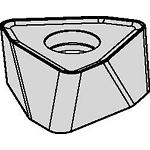
| ISO Catalog ID | WOEJ090512SRGD |
| ANSI Catalog ID | WOEJ090512SRGD |
| Grade | KCPM40 |
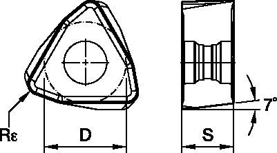
| [D] Insert IC Size | 8.9 mm |
| [D] Insert IC Size | 0.35 in |
| [S] Insert Thickness | 5.4 mm |
| [S] Insert Thickness | 0.213 in |
| [Rε] Corner Radius | 1.2 mm |
| [Rε] Corner Radius | 0.047 in |
| Cutting Edges per Insert | 6 |
Grades

KCPM40
Coated carbide grade with an advanced PVD TiAlN/AlCrN coating. Tough substrate with excellent capability at higher temperatures. KCPM40™ is the first choice for milling steel and stainless steel. Good thermal shock resistance makes this grade ideal for both wet and dry machining. Primarily for use in general and heavy machining.
Create Solution to calculate Feeds and Speeds
After creating a solution just choose the Feeds & Speeds icon and our system will provide recommendations. You can customize the information by adding your machine and specifications or make adjustments using the sliders.
| Insert Geometry | Recommended Starting Feed per Tooth (Fz) in Relation to % of Radial Engagement (ae) | Insert Geometry | ||||||||||||||
| 5% | 10% | 20% | 30% | 40–100% | ||||||||||||
| .S..GD | 1,15 | 2,42 | 3,84 | 0,82 | 1,71 | 2,67 | 0,61 | 1,26 | 1,96 | 0,53 | 1,10 | 1,70 | 0,49 | 1,01 | 1,55 | .S..GD |
| .S..HD | 1,15 | 2,78 | 4,27 | 0,82 | 1,96 | 2,94 | 0,61 | 1,44 | 2,16 | 0,53 | 1,26 | 1,87 | 0,49 | 1,15 | 1,71 | .S..HD |
| Light | General | Heavy |
| Light | General | Heavy |
| Insert Geometry | Recommended Starting Feed per Tooth (Fz) in Relation to % of Radial Engagement (ae) | Insert Geometry | ||||||||||||||
| 5% | 10% | 20% | 30% | 40–100% | ||||||||||||
| .S..GD | .045 | .089 | .141 | .032 | .063 | .098 | .024 | .047 | .072 | .021 | .040 | .063 | .019 | .037 | .057 | .S..GD |
| .S..HD | .045 | .109 | .168 | .032 | .077 | .116 | .024 | .057 | .085 | .021 | .049 | .074 | .019 | .045 | .067 | .S..HD |
| Material Group | KC522M | KC725M | KCK15 | KCPK30 | |||||||||
| P | 1 | 395 | 345 | 325 | 315 | 275 | 255 | – | – | – | 545 | 475 | 440 |
| 2 | 330 | 290 | 240 | 260 | 230 | 195 | – | – | – | 335 | 305 | 275 | |
| 3 | 305 | 255 | 215 | 240 | 205 | 170 | – | – | – | 305 | 275 | 250 | |
| 4 | 270 | 225 | 180 | 215 | 180 | 145 | – | – | – | 225 | 210 | 190 | |
| 5 | 225 | 200 | 180 | 180 | 160 | 145 | – | – | – | 310 | 275 | 255 | |
| 6 | 200 | 150 | 120 | 160 | 120 | 95 | – | – | – | 190 | 165 | – | |
| M | 1 | 245 | 215 | 200 | 205 | 180 | 165 | – | – | – | 250 | 220 | 190 |
| 2 | 225 | 190 | 160 | 185 | 160 | 130 | – | – | – | 225 | 195 | 170 | |
| 3 | 170 | 145 | 115 | 140 | 120 | 95 | – | – | – | 175 | 160 | 140 | |
| K | 1 | 275 | 250 | 220 | – | – | – | 505 | 460 | 410 | 355 | 320 | 285 |
| 2 | 215 | 195 | 180 | – | – | – | 400 | 355 | 330 | 280 | 255 | 230 | |
| 3 | 180 | 160 | 145 | – | – | – | 335 | 300 | 275 | 235 | 210 | 195 | |
| N | 1 | – | – | – | – | – | – | – | – | – | – | – | – |
| 2 | – | – | – | – | – | – | – | – | – | – | – | – | |
| S | 1 | 50 | 45 | 35 | 45 | 35 | 30 | – | – | – | – | – | – |
| 2 | 50 | 45 | 35 | 45 | 35 | 30 | – | – | – | – | – | – | |
| 3 | 60 | 50 | 35 | 55 | 45 | 30 | – | – | – | – | – | – | |
| 4 | 85 | 60 | 45 | 75 | 55 | 35 | – | – | – | – | – | – | |
| H | 1 | 145 | 110 | 85 | – | – | – | – | – | – | – | – | – |
| 2 | – | – | – | – | – | – | – | – | – | – | – | – | |
| 3 | – | – | – | – | – | – | – | – | – | – | – | – | |
| cutter type | catalog number | recommended ramping angle (for continuous ramping process) | max ramp angle when Ap max (not for continuous ramping process) | max ramp angle for 360° helical interpolation | min hole diameter (DH min) | max flat-bottom hole diameter (DH1 max) | max diameter (no flat bottom) |
| Screw-On | KF2X100W0902M12L138 | 3.5° | 5.2° | 3.1° | 1.291 | 1.35 | 2.0 |
| KF2X125W0902M16L169 | 1.9° | 2.8° | 1.7° | 1.813 | 1.87 | 2.5 | |
| KF2X125W0903M16L169 | 1.9° | 2.8° | 1.7° | 1.813 | 1.87 | 2.5 | |
| KF2X150W0903M16L169 | 1.4° | 2.1° | 1.2° | 2.310 | 2.37 | 3.0 | |
| KF2X150W0904M16L169 | 1.4° | 2.1° | 1.2° | 2.310 | 2.37 | 3.0 | |
| End Mills | KF2X100W0902C100L600 | 3.5° | 5.2° | 3.1° | 1.291 | 1.35 | 2.0 |
| KF2X100W0902C100L800 | 3.5° | 5.2° | 3.1° | 1.291 | 1.35 | 2.0 | |
| KF2X125W0903C125L600 | 1.9° | 2.8° | 1.7° | 1.813 | 1.87 | 2.5 | |
| KF2X125W0903C125L800 | 1.9° | 2.8° | 1.7° | 1.813 | 1.87 | 2.5 | |
| KF2X150W0903C125L600 | 1.4° | 2.1° | 1.2° | 2.310 | 2.37 | 3.0 | |
| KF2X150W0903C125L800 | 1.4° | 2.1° | 1.2° | 2.310 | 2.37 | 3.0 | |
| Face Mills | KF2X150W0904S050L157 | 1.4° | 2.1° | 1.2° | 2.310 | 2.37 | 3.0 |
| KF2X200W0905S075L157 | 1.0° | 1.4° | 0.8° | 3.307 | 3.37 | 4.0 | |
| KF2X200W0906S075L157 | 1.0° | 1.4° | 0.8° | 3.307 | 3.37 | 4.0 | |
| KF2X250W0906S075L175 | 0.7° | 1.1° | 0.6° | 4.305 | 4.36 | 5.0 | |
| KF2X300W0907S100L175 | 0.6° | 1.0° | 0.5° | 5.303 | 5.36 | 6.0 | |
| KF2X300W0907S125L200 | 0.6° | 1.0° | 0.5° | 5.303 | 5.36 | 6.0 |
| Rt | Wt | t |
| .110 | .312 | .045 |
| cutter type | catalog number | recommended ramping angle (for continuous ramping process) | max ramp angle when Ap max (not for continuous ramping process) | max ramp angle for 360° helical interpolation | min hole diameter (DH min) | max flat-bottom hole diameter (DH1 max) | max diameter (no flat bottom) |
| Screw-On | KF2X2X25Z02M12WO09 | 3.6° | 5.4° | 3.1° | 26,5 | 33,7 | 50 |
| KF2X32Z03M16WO09 | 1.8° | 2.7° | 1.7° | 41,2 | 48,4 | 64 | |
| KF2X35Z03M16WO09 | 1.6° | 2.4° | 1.4° | 46,8 | 54,0 | 70 | |
| KF2X42Z04M16WO09 | 1.2° | 1.9° | 0.8° | 68,7 | 75,9 | 84 | |
| End Mills | KF2X25Z02A25WO09L140 | 3.6° | 5.4° | 3.1° | 26,5 | 33,7 | 50 |
| KF2X25Z02A25WO09L200 | 3.6° | 5.4° | 3.1° | 26,5 | 33,7 | 50 | |
| KF2X25Z02A25WO09L300 | 3.6° | 5.4° | 3.1° | 26,5 | 33,7 | 50 | |
| KF2X28Z02A25WO09L200 | 3.1° | 4.6° | 2.5° | 31,6 | 38,8 | 56 | |
| KF2X32Z03A32WO09L150 | 1.8° | 2.7° | 1.7° | 41,2 | 48,4 | 64 | |
| KF2X32Z03A32WO09L200 | 1.8° | 2.7° | 1.7° | 41,2 | 48,4 | 64 | |
| KF2X32Z03A32WO09L300 | 1.8° | 2.7° | 1.7° | 41,2 | 48,4 | 64 | |
| KF2X35Z03A32WO09L200 | 1.6° | 2.4° | 1.4° | 46,8 | 54,0 | 70 | |
| Face Mills | KF2X40Z04WO09 | 1.3° | 2.0° | 1.2° | 56,4 | 63,6 | 80 |
| KF2X50Z05WO09 | 1.0° | 1.5° | 0.8° | 76,7 | 83,9 | 100 | |
| KF2X52Z05WO09 | 1.0° | 1.4° | 0.8° | 80,7 | 87,9 | 104 | |
| KF2X63Z05S22WO09 | 0.8° | 1.2° | 0.6° | 102,7 | 109,9 | 126 | |
| KF2X63Z05WO09 | 0.8° | 1.2° | 0.6° | 102,7 | 109,9 | 126 | |
| KF2X66Z06S22WO09 | 0.7° | 1.1° | 0.5° | 108,7 | 115,9 | 132 | |
| KF2X66Z06WO09 | 0.7° | 1.1° | 0.5° | 108,7 | 115,9 | 132 | |
| KF2X80Z07WO09 | 0.6° | 0.9° | 0.4° | 136,6 | 143,8 | 160 |
| diameter | max ramp angle | max ramp angle for 360° helical interpolation | max plunge depth | min hole diameter (DH min) | max flat-bottom hole diameter (DH1 max) | max diameter (no flat bottom) |
| 1.50 | 5.5° | 1.93° | 0.076 | 1.90 | 2.22 | 3.00 |
| 2.00 | 4.4° | 1.18° | 0.076 | 2.86 | 3.22 | 4.00 |
| 2.50 | 3.0° | 0.85° | 0.076 | 3.85 | 4.22 | 5.00 |
| 3.00 | 2.3° | 0.67° | 0.076 | 4.84 | 5.21 | 6.00 |
| 4.00 | 1.6° | 0.47° | 0.076 | 6.84 | 7.21 | 8.00 |
| 5.00 | 1.2° | 0.36° | 0.076 | 8.84 | 9.21 | 10.00 |
| Material Group | Light | General | Heavy | |||
| – | (Light geometry) | – | (Strong geometry) | |||
| – | wear |  | toughness | |||
| – | Geometry | Grade | Geometry | Grade | Geometry | Grade |
| P1–P2 | .S..GD | KCPK30 | .S..GD | KCPM40 | .S..HD | KCPM40 |
| P3–P4 | .S..GD | KCPK30 | .S..GD | KCPM40 | .S..HD | KCPM40 |
| P5–P6 | .S..GD | KCPK30 | .S..GD | KC725M | .S..HD | KC725M |
| M1–M2 | .S..GD | KC522M | .S..GD | KC725M | .S..HD | KC725M |
| M3 | .S..GD | KCPK30 | .S..GD | KCPM40 | .S..HD | KCPM40 |
| K1–K2 | .S..HD | KCK15 | .S..HD | KCK15 | .S..HD | KCK15 |
| K3 | .S..GD | KCPK30 | .S..HD | KCK15 | .S..HD | KCPK30 |
| N1–N2 | – | – | – | – | – | – |
| N3 | – | – | – | – | – | – |
| S1–S2 | .S..GD | KC522M | .S..GD | KC725M | .S..HD | KC725M |
| S3 | .S..GD | KC725M | .S..GD | KCPM40 | .S..HD | KCPM40 |
| S4 | .S..GD | KC522M | .S..HD | KC522M | .S..HD | KC725M |
| H1 | – | – | – | – | – | – |
| Material Group | Light | General | Heavy | |||
| (Light geometry) | (Strong geometry) | |||||
| wear | | toughness | ||||
| Geometry | Grade | Geometry | Grade | Geometry | Grade | |
| P1–P2 | .S..GD | KCPK30 | .S..GD | KCPM40 | .S..HD | KCPM40 |
| P3–P4 | .S..GD | KCPK30 | .S..GD | KCPM40 | .S..HD | KCPM40 |
| P5–P6 | .S..GD | KCPK30 | .S..GD | KC725M | .S..HD | KC725M |
| M1–M2 | .S..GD | KC522M | .S..GD | KC725M | .S..HD | KC725M |
| M3 | .S..GD | KCPK30 | .S..GD | KCPM40 | .S..HD | KCPM40 |
| K1–K2 | .S..HD | KCK15 | .S..HD | KCK15 | .S..HD | KCK15 |
| K3 | .S..GD | KCPK30 | .S..HD | KCK15 | .S..HD | KCPK30 |
| N1–N2 | – | – | – | – | – | – |
| N3 | – | – | – | – | – | – |
| S1–S2 | .S..GD | KC522M | .S..GD | KC725M | .S..HD | KC725M |
| S3 | .S..GD | KC725M | .S..GD | KCPM40 | .S..HD | KCPM40 |
| S4 | .S..GD | KC522M | .S..HD | KC522M | .S..HD | KC725M |
| H1 | – | – | – | – | – | – |
I have read and accepted the Terms & Conditions of use


ISO Catalog Number
ANSI Catalog Number
to find similar products.Please select a file to download
Models
Product data
. Please enter the desired qty for the material(s) you want to include in your promotion or Proceed Without Promotion and only your base materials will be added to the cart.
Minimum quantity should be
| SAP Material Number | ISO Catalog Number | Grade |
|---|
You are about to leave the Solution building process.
Are you sure you want to leave?