KNS®

Read More

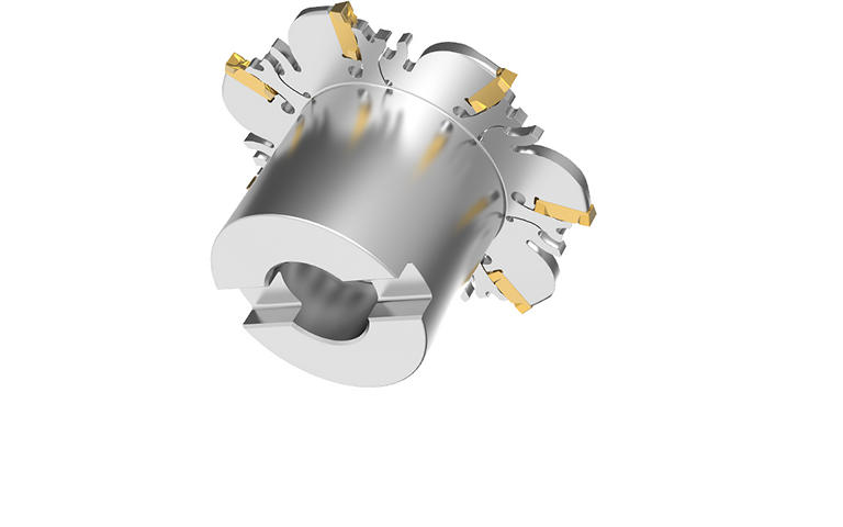
Podwójny rowek typu V oraz gniazdo utrzymują płytkę na miejscu i minimalizują bicie promieniowe.
Stabilne warunki skrawania zapewniają w rezultacie dużą dokładność szerokości rowka i wysoką powtarzalność.
Wyjątkowy mechanizm samozaciskowy zapewnia łatwą wymianę płytek.
Pozytywowa geometria SGP łamacza wióra w zastosowaniach od obróbki lekkiej do ciężkiej zapewnia płynną pracę narzędzia i skuteczne odprowadzanie wiórów.
Filtry
Filtry
Wyświetl filtry w
Metryczne
Calowe
Workpiece Material
Workpiece Material
-
P Steel (126)
-
P0Low-Carbon Steels, Long Chipping C < .25%; <125 HB; <530 N/mm^2 UTS (126)
-
P1Low-Carbon Steels, Short Chipping C < .25%; <125 HB; <530 N/mm^2 UTS (126)
-
P2Medium and High Carbon Steels C < .25%; <220 HB; <25 HRC; >530 N/mm^2 UTS (126)
-
P3Alloy Steels & Tool Steels C > .25%; <330 HB; <35 HRC; 600-850 N/mm^2 UTS (126)
-
P4Alloy Steels & Tool Steels C > .25%; 350-420 HB; 35-43 HRC; 850-1400 N/mm^2 UTS (126)
-
P5Ferritic, Martensitic, and PH Stainless Steels <330 HB; <35 HRC; 600-900 N/mm^2 UTS (126)
-
P6High Strength Ferritic, Martensitic, and PH Stainless Steels 350-450 HB; 35-43 HRC; 900-2400 N/mm^2 UTS (126)
-
-
M Stainless Steel (126)
-
M1Austenitic Stainless Steel 130-200 HB; <600 N/mm^2 UTS (126)
-
M2High Strength Austenitic Stainless and Cast Stainless Steels 150-230 HB; <25 HRC; >600 N/mm^2 UTS (126)
-
M3Duplex Stainless Steel 135-275 HB; <30 HRC; 500-1200 N/mm^2 UTS (126)
-
-
K Cast Iron (110)
-
K1Gray Cast Iron 120-290 HB; <32 HRC; 125-500 N/mm^2 UTS (110)
-
K2Low and Medium Strength CGI and Ductile Irons 130-260 HB; <28 HRC; <600 N/mm^2 UTS (110)
-
K3High Strength Ductile and Austempered Ductile Iron 180-350 HB; <43 HRC; >600 N/mm^2 UTS (110)
-
-
N Non-Ferrous Materials (92)
-
N1Wrought Aluminum (92)
-
N2Low-Silicon Aluminum Alloys and Magnesium Alloys Si <12.2% (92)
-
N3High-Silicon Aluminum Alloys Si >12.2% (92)
-
-
S High-Temp Alloys (126)
-
S1Iron-Based, Heat-Resistant Alloys 160-260 HB; 25-48 HRC; 500-1200 N/mm^2 UTS (108)
-
S2Cobalt-Based, Heat-Resistant Alloys 250-450 HB; 25-48 HRC; 1000-1450 N/mm^2 UTS (108)
-
S3Nickel-Based, Heat Resistant Alloys 160-450 HB; <48 HRC; 600-1700 N/mm^2 UTS (108)
-
S4Titanium and Titanium Alloys 300-400 HB; 33-43 HRC; 900-1600 N/mm^2 UTS (126)
-
-
H Hardened Materials (74)
-
H1Hardened Materials 44-48 HRC (74)
-
Applications
Applications
-
Slot Milling (74)
-
Slot Side (74)
-
Slot Square End (74)
Cutting Diameter
Cutting Diameter
-
2.48 in (1)
-
2.5 in (1)
-
3.0 in (2)
-
3.15 in (2)
-
3.938 in (10)
-
4.0 in (10)
-
4.921 in (11)
-
5.0 in (11)
-
6.0 in (5)
-
6.299 in (5)
-
7.875 in (5)
-
8.0 in (5)
-
9.843 in (3)
-
10.0 in (3)
do
Cutting Diameter
Cutting Diameter
-
63.0 mm (1)
-
63.5 mm (1)
-
76.2 mm (2)
-
80.0 mm (2)
-
100.0 mm (10)
-
101.601 mm (10)
-
125.0 mm (11)
-
127.0 mm (11)
-
152.4 mm (5)
-
160.0 mm (5)
-
200.0 mm (5)
-
203.201 mm (5)
-
250.0 mm (3)
-
254.0 mm (3)
do
Reach
Reach
-
1.782 in (1)
-
1.792 in (1)
-
1.821 in (1)
-
2.0 in (1)
-
2.011 in (1)
-
2.039 in (1)
-
2.053 in (1)
-
2.067 in (1)
-
2.083 in (1)
-
2.1 in (1)
-
2.415 in (1)
-
2.43 in (1)
-
2.445 in (1)
-
2.463 in (1)
do
Reach
Reach
-
45.25 mm (1)
-
45.5 mm (1)
-
46.25 mm (1)
-
50.801 mm (1)
-
51.051 mm (1)
-
51.801 mm (1)
-
52.151 mm (1)
-
52.5 mm (1)
-
52.901 mm (1)
-
53.35 mm (1)
-
61.35 mm (1)
-
61.7 mm (1)
-
62.1 mm (1)
-
62.551 mm (1)
do
Tool Cutting Edge Angle
Tool Cutting Edge Angle
-
90.0 (74)
do
Connection Style
Connection Style
-
A-Socket Head Cap Screw (14)
Number of Flutes
Number of Flutes
-
10 (3)
-
11 (8)
-
12 (3)
-
13 (5)
-
14 (2)
-
15 (4)
-
17 (6)
-
4 (1)
-
5 (7)
-
6 (6)
-
7 (14)
-
8 (11)
-
9 (4)
Cutting Edges Per Insert
Cutting Edges Per Insert
-
1.0 (95)
-
2.0 (83)
do
Internal Coolant Capability
Internal Coolant Capability
Over All Length [L]
Over All Length [L]
-
1.782 in (1)
-
1.792 in (1)
-
1.821 in (1)
-
2.0 in (1)
-
2.011 in (1)
-
2.039 in (1)
-
2.053 in (1)
-
2.067 in (1)
-
2.083 in (1)
-
2.1 in (1)
-
2.415 in (1)
-
2.43 in (1)
-
2.445 in (1)
-
2.463 in (1)
do
Over All Length [L]
Over All Length [L]
-
45.25 mm (1)
-
45.5 mm (1)
-
46.25 mm (1)
-
50.801 mm (1)
-
51.051 mm (1)
-
51.801 mm (1)
-
52.151 mm (1)
-
52.5 mm (1)
-
52.901 mm (1)
-
53.35 mm (1)
-
61.35 mm (1)
-
61.7 mm (1)
-
62.1 mm (1)
-
62.551 mm (1)
do
Corner Radius
Corner Radius
-
0.006 in (27)
-
0.008 in (61)
-
0.012 in (27)
-
0.016 in (24)
-
0.06 in (12)
-
0.063 in (13)
-
0.079 in (14)
do
Corner Radius
Corner Radius
-
0.151 mm (27)
-
0.2 mm (61)
-
0.301 mm (27)
-
0.4 mm (24)
-
1.5 mm (12)
-
1.6 mm (13)
-
2.0 mm (14)
do
application
Grade Of Cutting Tool
Grade Of Cutting Tool
-
KC522M (74)
-
KCPK30 (92)
-
KCPM40 (90)
-
KCU25 (92)
Hand Of Tool
Hand Of Tool
-
N (60)
-
R (14)
Wiper Insert
Wiper Insert
-
N (52)
frontEnd
Cutting Width
Cutting Width
-
0.063 in (13)
-
0.079 in (8)
-
0.088 in (14)
-
0.095 in (8)
-
0.098 in (13)
-
0.119 in (18)
-
0.125 in (19)
-
0.157 in (20)
-
0.188 in (12)
-
0.197 in (15)
-
0.237 in (18)
-
0.25 in (18)
do
Cutting Width
Cutting Width
-
1.6 mm (13)
-
2.0 mm (8)
-
2.2 mm (14)
-
2.401 mm (8)
-
2.5 mm (13)
-
3.0 mm (18)
-
3.176 mm (19)
-
4.0 mm (20)
-
4.775 mm (12)
-
5.0 mm (15)
-
6.0 mm (18)
-
6.351 mm (18)
do
Maximum Cutting Depth
Maximum Cutting Depth
-
0.376 in (10)
-
0.875 in (2)
-
0.906 in (1)
-
0.972 in (3)
-
1.012 in (3)
-
1.051 in (1)
-
1.094 in (4)
-
1.131 in (1)
-
1.156 in (6)
-
1.268 in (5)
-
1.504 in (6)
-
1.532 in (6)
-
1.879 in (4)
-
1.917 in (1)
-
2.008 in (5)
-
2.566 in (4)
-
2.75 in (1)
-
2.795 in (5)
-
3.567 in (1)
-
3.594 in (1)
-
3.605 in (1)
-
3.781 in (3)
do
Maximum Cutting Depth
Maximum Cutting Depth
-
9.55 mm (10)
-
22.225 mm (2)
-
23.0 mm (1)
-
24.701 mm (3)
-
25.701 mm (3)
-
26.701 mm (1)
-
27.776 mm (4)
-
28.701 mm (1)
-
29.35 mm (6)
-
32.2 mm (5)
-
38.2 mm (6)
-
38.901 mm (6)
-
47.7 mm (4)
-
48.7 mm (1)
-
51.0 mm (5)
-
65.175 mm (4)
-
69.851 mm (1)
-
71.0 mm (5)
-
90.575 mm (1)
-
91.275 mm (1)
-
91.575 mm (1)
-
96.0 mm (3)
do
Maximum Cutting Insert Depth
Maximum Cutting Insert Depth
-
7.601 mm (13)
-
9.175 mm (11)
-
11.55 mm (13)
-
12.675 mm (15)
-
12.75 mm (15)
-
14.5 mm (15)
-
14.525 mm (12)
-
14.75 mm (13)
do
Maximum Cutting Insert Depth
Maximum Cutting Insert Depth
-
0.299 in (13)
-
0.361 in (11)
-
0.455 in (13)
-
0.499 in (15)
-
0.502 in (15)
-
0.572 in (15)
-
0.573 in (12)
-
0.581 in (13)
do
Center Cutting
Center Cutting
insertGeometry
Shape
Shape
-
PRISMATIC (52)
Insert Seat Size
Insert Seat Size
-
12 (3)
-
16 (6)
-
21 (11)
-
27 (9)
-
34 (8)
-
42 (3)
-
51 (12)
Cutting Tool Material
Cutting Tool Material
-
H W (52)
backEnd
Connection Type
Connection Type
-
ARBOR (60)
-
SHELL MILL (14)
Back-End Diameter
Back-End Diameter
-
15.875 mm (1)
-
15.9 mm (1)
-
16.0 mm (2)
-
22.0 mm (9)
-
25.401 mm (11)
-
27.0 mm (2)
-
31.75 mm (1)
-
31.8 mm (10)
-
32.0 mm (11)
-
38.1 mm (5)
-
40.0 mm (13)
-
50.801 mm (8)
do
Back-End Diameter
Back-End Diameter
-
0.625 in (1)
-
0.626 in (1)
-
0.63 in (2)
-
0.866 in (9)
-
1.0 in (11)
-
1.063 in (2)
-
1.25 in (1)
-
1.252 in (10)
-
1.26 in (11)
-
1.5 in (5)
-
1.575 in (13)
-
2.0 in (8)
do
No filters matching ""

