Sending to SolidCAM in progress...

Downloaded file will be available after import in the SolidCAM tool library.

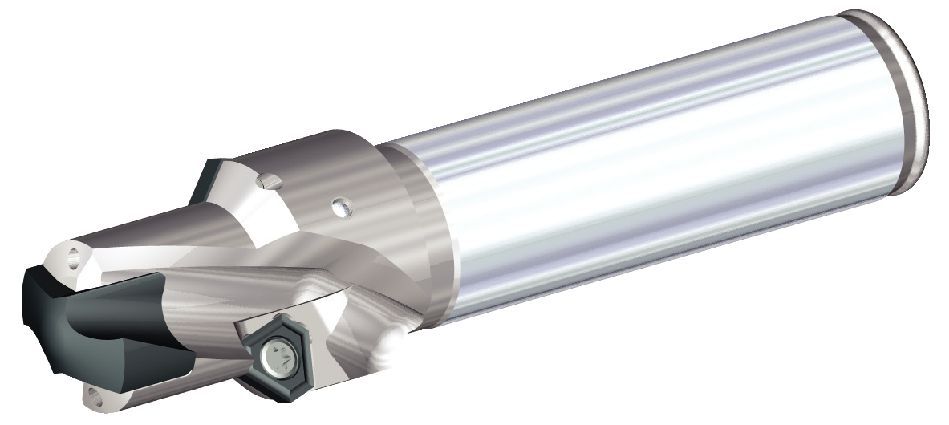
KSEM ™ z narożem fazowanym 45° • Korpusy z chwytem walcowym
Select the files you wish to request
Downloads
Request {{cadTool}} format
{{cadTool}} format is not available

Korpusy KSEM™ • 1 x D • Chwyt walcowy z narożem fazowanym • Calowe

KSEM ™ z narożem fazowanym 45° • Korpusy z chwytem walcowym

Metryczne
Calowe
SAP Material Number 2224002
ISO Catalog Number KSEM0709R1SS075F45
ANSI Catalog Number KSEM0709R1SS075F45
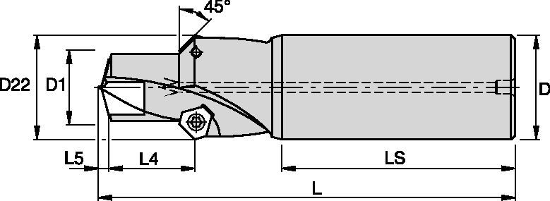
[D1] Drill Diameter M 18.01 mm
[D1] Drill Diameter M .7091 in
[D1MAX] Drill Diameter Maximum 19.999 mm
[D1MAX] Drill Diameter Maximum .7873 in
[D22] Cut Diameter 2 24.303 mm
[D22] Cut Diameter 2 .9568 in
[L] Overall Length 94.98 mm
[L] Overall Length 3.739 in
[L4] Maximum Drilling Depth 20.64 mm
[L4] Maximum Drilling Depth .8127 in
[L5] Drill Point Length 2.64 mm
[L5] Drill Point Length .104 in
[LS] Shank Length 50.8 mm
[LS] Shank Length 2 in
[D] Adapter / Shank / Bore Diameter 19.05 mm
[D] Adapter / Shank / Bore Diameter .75 in
[SSC] Insert Seat Size 2
Gage Insert TPGX1102ZPRGD
Zobacz wszystkie warianty produktów

Zastosowania

  • Counter Sinking/ Stroke ChamferingCounter Sinking/ Stroke Chamfering
  • Drilling - Through CoolantDrilling - Through Coolant
  • Shank - Cylindrical  Plain ≤h6Shank - Cylindrical Plain ≤h6

Materiały przedmiotu obrabianego

P Steel
M Stainless Steel
K Cast Iron
N Non-Ferrous
S High-Temp Alloys

Właściwości i zalety

  • Annealed steel bodies for reliable drilling and chamfering with high tool life and increased productivity.

  • Very rigid pocket seat: KSEM™ offers a four-wall pocket on the main cutting insert providing insert stability, hole quality, and increased tool life.

  • Two pockets for chamfering using TPGX chamfer inserts. Highly stable design for high quality and increased productivity.

  • Through coolant close to the cutting edge for improved tool life, hole finish, and chip removal.

  • Insert blades must be of the same seat size as the body it should be used on. For each seat size, there is a preferred choice (=BEST FIT) of bodies for a particular insert diameter. Overhang of the insert to the body shall not exceed 0.0098” (0,25mm) per side. Higher overhang is possible but will compromise performance, rigidity and efficient chip evacuation. We recommend to always use the closest fit possible, especially when machining long chipping materials.

Strona maszyny

ładowanie...

Strona przedmiotu obrabianego

ładowanie...
Zamierzasz dodać do strony Moje rozwiązania. Czy chcesz kontynuować?
product-image
Please adjust the following properties from

Oznaczenie katalogowe ISO

Oznaczenie katalogowe ANSI

to find similar products.

Models

Powinieneś być zalogowany, aby zobaczyć informacje o swoim pulpicie nawigacyjnym
Session expired due to inactivity, please login again
Produkty (), które próbowałeś dodać do koszyka, są niedostępne, skontaktuj się z działem obsługi klienta.
produkty dodane do koszyka

. Please enter the desired qty for the material(s) you want to include in your promotion or Proceed Without Promotion and only your base materials will be added to the cart.

Minimum quantity should be

SAP Material Number Oznaczenie katalogowe ISO Gatunek    

Thank you for your registration, pending approval & completion of the registration, your access is currently limited. Full utilization of product search capabilities & collaboration space is available and will remain. Please allow 2 business days for registration completion.

Dziękujemy za pomyślną rejestrację. Możesz teraz zalogować się i korzystać z witryny

You are about to leave the Solution building process.

Are you sure you want to leave?