Produkt podobny do:
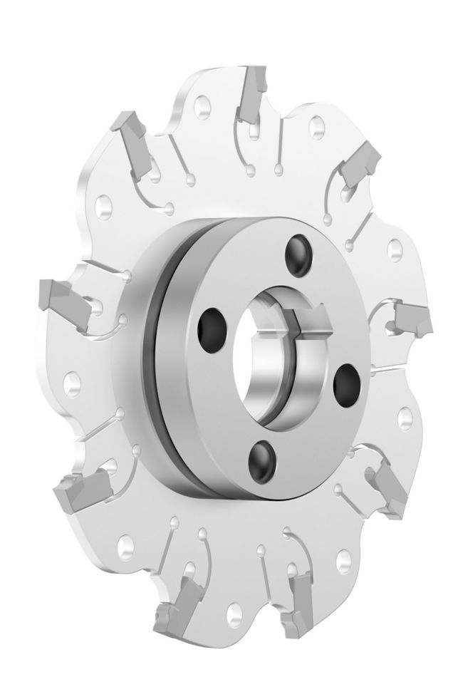
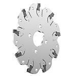
KVNS™ A2™ • Arbor Mount • Metric
Slot milling cutter for multiple materials
Nr materiału1246126
Nr katalogowy ISO4.97080130Nr katalogowy ANSI4.97080130
- P Steel
- M Stainless Steel
- K Cast Iron
- N Non-Ferrous
- S High-Temp Alloys
- .caption
Slotting: Side with AE/AP dimensions
Sending to {{cadTool}} in progress...
Downloaded file will be available after import in the {{cadTool}} tool library.
- Podsumowanie
- Parametry skrawania
- Do pobrania
- Pasujace produkty - strona maszyny
- Pasujace produkty - strona przedmiotu obrabianego
- Części zamienne
- Opinia
- Q&A
| Nr materiału | 1246126 |
| Nr katalogowy ISO | 4.97080130 |
| Nr katalogowy ANSI | 4.97080130 |
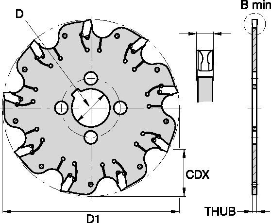
| [BM] Cutting Width Minimum | 3 mm |
| [BM] Cutting Width Minimum | 0.1181 in |
| [D1] Effective Cutting Diameter | 80 mm |
| [D1] Effective Cutting Diameter | 3.15 in |
| [CDX] Radial Maximum Depth of Cut | 21 mm |
| [CDX] Radial Maximum Depth of Cut | 0.8268 in |
| [D] Adapter / Shank / Bore Diameter | 16 mm |
| [D] Adapter / Shank / Bore Diameter | 0.6299 in |
| [THUB] Hub Thickness | 2.4 mm |
| [THUB] Hub Thickness | 0.0945 in |
| Number of Inserts | 6 |
| Weight Kilograms | 0.07 |
| Gage Insert | 3.90030____ |
| Max RPM | 4000 |
Materiały przedmiotu obrabianego
- Steel
- Stainless Steel
- Cast Iron
- Non-Ferrous
- High-Temp Alloys
- .caption
Zastosowania
Slotting: Side with AE/AP dimensions
Właściwości i zalety
- Self-clamping insert seat with fixed stop.
- Excellent for all flat-bottom slotting and cut-off operations.
- Two drive rings required for each cutter body. They must be ordered separately, and in pairs of two.
- For cutter diameters 200mm and 250mm support rings are optional (instead of drive rings). Support rings also must be ordered separately, and in pairs of two.
Złóż nowe rozwiązanie aby obliczyc parametry posuwu i prędkości
Po złóżeniu rozwiązania wybierz ikonę "Posuwy i prędkości" a system pokaże rekomendowane wartości. Możesz doprecyzować wyniki dodając maszynę i jej specyfikacje lub zmień wartości początkowe Używając suwaki.
Posuwy
Zalecane wyjściowe wartości posuwu [mm]
| KVNS™ A2™ Series • Recommended Starting Feeds [mm/th] | |||||||||||||||
| Geometria płytki | Rekomendowane początkowe wartości posuwu na ząb (Fz) w relacji do % zaangażowania promieniowego (ae) | ||||||||||||||
| 5% | 10% | 20% | 30% | 40–100% | |||||||||||
| L | M | H | L | M | H | L | M | H | L | M | H | L | M | H | |
| .S..GD | 0,23 | 0,46 | 0,71 | 0,17 | 0,33 | 0,51 | 0,13 | 0,25 | 0,38 | 0,11 | 0,22 | 0,33 | 0,10 | 0,20 | 0,30 |
| .S..GB | 0,23 | 0,46 | 0,74 | 0,17 | 0,33 | 0,54 | 0,13 | 0,25 | 0,40 | 0,11 | 0,22 | 0,35 | 0,10 | 0,20 | 0,32 |
| L = Light Machining; M = Medium Machining; H = Heavy Machining NOTE: Use "Light Machining" values as starting feed rate. | |||||||||||||||
Recommended Starting Feeds [IPT]
| KVNS™ A2™ Series • Recommended Starting Feeds [IPT] | |||||||||||||||
| Geometria płytki | Rekomendowane początkowe wartości posuwu na ząb (Fz) w relacji do % zaangażowania promieniowego (ae) | ||||||||||||||
| 5% | 10% | 20% | 30% | 40–100% | |||||||||||
| L | M | H | L | M | H | L | M | H | L | M | H | L | M | H | |
| .S..GD | 0.009 | 0.017 | 0.026 | 0.007 | 0.013 | 0.019 | 0.005 | 0.009 | 0.014 | 0.004 | 0.008 | 0.012 | 0.004 | 0.008 | 0.011 |
| .S..GB | 0.009 | 0.017 | 0.028 | 0.007 | 0.013 | 0.020 | 0.005 | 0.009 | 0.015 | 0.004 | 0.008 | 0.013 | 0.004 | 0.008 | 0.012 |
| L = Light Machining; M = Medium Machining; H = Heavy Machining NOTE: Use "Light Machining" values as starting feed rate. | |||||||||||||||
Prędkości
Zalecane wyjściowe wartości prędkości skrawania [m/min]
| KVNS™ A2™ Series • Recommended Starting Speed [m/min] | |||||||
| Gatunek | KCPK30 | KMF | |||||
| Grubość wióra hex mm | Min. | Maks. | Min. | Maks. | |||
| Grupa materiałowa | Maks. | Początek | Min. | Maks. | Początek | Min. | |
| P | 1 | 455 | 395 | 370 | – | – | – |
| 2 | 280 | 255 | 230 | – | – | – | |
| 3 | 255 | 230 | 205 | – | – | – | |
| 4 | 225 | 185 | 160 | – | – | – | |
| 5 | 190 | 170 | 150 | – | – | – | |
| 6 | 160 | 135 | 110 | – | – | – | |
| M | 1 | 205 | 185 | 155 | – | – | – |
| 2 | 185 | 160 | 140 | – | – | – | |
| 3 | 145 | 130 | 115 | – | – | – | |
| K | 1 | 295 | 265 | 240 | – | – | – |
| 2 | 235 | 210 | 190 | – | – | – | |
| 3 | 195 | 175 | 160 | – | – | – | |
| N | 1 | – | – | – | 335 | 298 | 271 |
| 2 | – | – | – | 335 | 298 | 271 | |
| 3 | – | – | – | 219 | 198 | 170 | |
| S | 1 | – | – | – | 30 | 24 | 20 |
| 2 | – | – | – | 30 | 24 | 20 | |
| 3 | – | – | – | 30 | 24 | 20 | |
| 4 | 50 | 45 | 35 | 24 | 24 | 24 | |
| H | 1 | – | – | – | – | – | – |
| Recommended Starting Speed are pointing to 90° Shoulder Milling . Starting Speed for Face and Copy Milling can be Increased by 20 %. As the average chip thickness increases, speed should be decreased. Material groups P, M, K and H show recommended starting speeds for dry machining. For wet machining, reduce speed by 20%. Material groups N and S show recommended starting speeds for wet machining. Not recommended for dry machining. | |||||||
Recommended Starting Speeds [SFM]
| KVNS™ A2™ Series • Recommended Starting Speed [SFM] | |||||||
| Gatunek | KCPK30 | KMF | |||||
| Chip Thickness hex Inch | Min. | Maks. | Min. | Maks. | |||
| Grupa materiałowa | Maks. | Początek | Min. | Maks. | Początek | Min. | |
| P | 1 | 1495 | 1295 | 1215 | – | – | – |
| 2 | 920 | 835 | 755 | – | – | – | |
| 3 | 835 | 755 | 675 | – | – | – | |
| 4 | 740 | 605 | 525 | – | – | – | |
| 5 | 625 | 560 | 490 | – | – | – | |
| 6 | 525 | 445 | 360 | – | – | – | |
| M | 1 | 675 | 605 | 510 | – | – | – |
| 2 | 605 | 525 | 460 | – | – | – | |
| 3 | 475 | 425 | 375 | – | – | – | |
| K | 1 | 970 | 870 | 785 | – | – | – |
| 2 | 770 | 690 | 625 | – | – | – | |
| 3 | 640 | 575 | 525 | – | – | – | |
| N | 1 | – | – | – | 1100 | 980 | 890 |
| 2 | – | – | – | 1100 | 980 | 890 | |
| 3 | – | – | – | 720 | 650 | 560 | |
| S | 1 | – | – | – | 100 | 80 | 65 |
| 2 | – | – | – | 100 | 80 | 65 | |
| 3 | – | – | – | 100 | 80 | 65 | |
| 4 | 165 | 150 | 115 | 80 | 80 | 80 | |
| H | 1 | – | – | – | – | – | – |
| Recommended Starting Speed are pointing to 90° Shoulder Milling . Starting Speed for Face and Copy Milling can be Increased by 20 %. As the average chip thickness increases, speed should be decreased. Material groups P, M, K and H show recommended starting speeds for dry machining. For wet machining, reduce speed by 20%. Material groups N and S show recommended starting speeds for wet machining. Not recommended for dry machining. | |||||||
Dobór płytek
Poradnik doboru płytek
| KVNS™ A2™ Slotting Cutters • Insert Selection Guide | ||||||
| Grupa materiałowa | Obróbka lekka | Obróbka średnia | Obróbka ciężka | |||
| – | (Lekka geometria) | (Zgrubna geometria) | ||||
| – | odporność na zużycie |  | ciągliwość | |||
| – | Geometria | Gatunek | Geometria | Gatunek | Geometria | Gatunek |
| P1-P2 | .S..GD | KCPK30 | .S..GD | KCPK30 | .S..GB | KCPK30 |
| P3-P4 | .S..GD | KCPK30 | .S..GD | KCPK30 | .S..GB | KCPK30 |
| P5-P6 | .S..GD | KCPK30 | .S..GB | KCPK30 | .S..GB | KCPK30 |
| M1-M2 | .S..GD | KCPK30 | .S..GD | KCPK30 | .S..GB | KCPK30 |
| M3 | .S..GD | KCPK30 | .S..GB | KCPK30 | .S..GB | KCPK30 |
| K1-K2 | .S..GD | KCPK30 | .S..GD | KCPK30 | .S..GB | KCPK30 |
| K3 | .S..GD | KCPK30 | .S..GD | KCPK30 | .S..GB | KCPK30 |
| N1-N2 | – | – | – | – | – | – |
| N3 | – | – | – | – | – | – |
| S1-S2 | – | – | – | – | – | – |
| S3 | – | – | – | – | – | – |
| S4 | – | – | – | – | – | – |
| H1 | – | – | – | – | – | – |
I have read and accepted the Terms & Conditions of use
CAD Drawings Models
Can’t find the file type you’re looking for?
Product data
