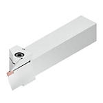
Beyond Evolution Integral Holders
Filters
Filters
View filters in
MetricInch
Workpiece Material
Workpiece Material
- P Steel (253)
- P0Low-Carbon Steels, Long Chipping C < .25%; <125 HB; <530 N/mm^2 UTS(253)
- P1Low-Carbon Steels, Short Chipping C < .25%; <125 HB; <530 N/mm^2 UTS(253)
- P2Medium and High Carbon Steels C < .25%; <220 HB; <25 HRC; >530 N/mm^2 UTS(253)
- P3Alloy Steels & Tool Steels C > .25%; <330 HB; <35 HRC; 600-850 N/mm^2 UTS(253)
- P4Alloy Steels & Tool Steels C > .25%; 350-420 HB; 35-43 HRC; 850-1400 N/mm^2 UTS(253)
- P5Ferritic, Martensitic, and PH Stainless Steels <330 HB; <35 HRC; 600-900 N/mm^2 UTS(253)
- P6High Strength Ferritic, Martensitic, and PH Stainless Steels 350-450 HB; 35-43 HRC; 900-2400 N/mm^2 UTS(253)
- M Stainless Steel (253)
- M1Austenitic Stainless Steel 130-200 HB; <600 N/mm^2 UTS(253)
- M2High Strength Austenitic Stainless and Cast Stainless Steels 150-230 HB; <25 HRC; >600 N/mm^2 UTS(253)
- M3Duplex Stainless Steel 135-275 HB; <30 HRC; 500-1200 N/mm^2 UTS(253)
- K Cast Iron (253)
- K1Gray Cast Iron 120-290 HB; <32 HRC; 125-500 N/mm^2 UTS(253)
- K2Low and Medium Strength CGI and Ductile Irons 130-260 HB; <28 HRC; <600 N/mm^2 UTS(253)
- K3High Strength Ductile and Austempered Ductile Iron 180-350 HB; <43 HRC; >600 N/mm^2 UTS(253)
- N Non-Ferrous Materials (253)
- N1Wrought Aluminum (253)
- N2Low-Silicon Aluminum Alloys and Magnesium Alloys Si <12.2%(253)
- N4Copper, Brass, Zinc-based on machinability index range of 70-100 (253)
- N5Nylon, Plastics, Rubbers, Phenolics, Resins, Fiberglass (253)
- N6Carbon, Graphite Composites, CFRP (253)
- S High-Temp Alloys (253)
- S1Iron-Based, Heat-Resistant Alloys 160-260 HB; 25-48 HRC; 500-1200 N/mm^2 UTS(253)
- S2Cobalt-Based, Heat-Resistant Alloys 250-450 HB; 25-48 HRC; 1000-1450 N/mm^2 UTS(253)
- S3Nickel-Based, Heat Resistant Alloys 160-450 HB; <48 HRC; 600-1700 N/mm^2 UTS(253)
- S4Titanium and Titanium Alloys 300-400 HB; 33-43 HRC; 900-1600 N/mm^2 UTS(253)
- H Hardened Materials (253)
- H1Hardened Materials 44-48 HRC(253)
- H2Hardened Materials 48-55 HRC(253)
Applications
Applications
Cut-Off (231)
Face Grooving (253)
Grooving (231)
Cutting Condition
Cutting Condition
- Heavily Interrupted Cut (253)
- Lightly Interrupted Cut (253)
- Smooth Cut (253)
Over All Length [L]
Over All Length [L]
- 114.3 mm(20)
- 125.0 mm(20)
- 150.0 mm(89)
- 152.4 mm(108)
- 170.0 mm(16)
to
Corner Radius
Corner Radius
- 0.0 mm(64)
- 0.2 mm(117)
- 0.3 mm(136)
- 0.4 mm(253)
- 0.8 mm(189)
- 1.5 mm(64)
- 1.55 mm(64)
- 1.575 mm(64)
- 1.6 mm(64)
- 1.65 mm(64)
- 2.0 mm(53)
- 2.075 mm(53)
- 2.375 mm(53)
- 2.45 mm(53)
- 2.5 mm(72)
- 2.55 mm(72)
- 2.575 mm(72)
- 3.0 mm(64)
- 3.05 mm(64)
- 3.075 mm(64)
- 3.175 mm(64)
- 3.25 mm(64)
to
Application
Minimum Depth of Cut
Minimum Feed
Grade Of Cutting Tool
Grade Of Cutting Tool
- K313 (253)
- KCK20B (253)
- KCM35B (189)
- KCP10B (253)
- KCP25B (253)
- KCP25C (253)
- KCS10B (189)
- KCU10 (253)
- KCU10B (253)
- KCU25 (253)
- KCU25B (253)
Hand Of Tool
Hand Of Tool
- L (127)
- R (126)
F Dimension
F Dimension
- 19.2 mm(5)
- 19.203 mm(1)
- 19.205 mm(1)
- 19.207 mm(1)
- 19.21 mm(11)
- 19.2106 mm(1)
- 20.178 mm(2)
- 20.179 mm(1)
- 20.18 mm(5)
- 20.181 mm(7)
- 20.182 mm(3)
- 20.183 mm(2)
- 25.18 mm(26)
- 25.182 mm(2)
- 25.183 mm(3)
- 25.184 mm(5)
- 25.185 mm(12)
- 25.19 mm(17)
- 25.2 mm(2)
- 25.204 mm(2)
- 25.206 mm(1)
- 25.21 mm(18)
- 25.2106 mm(1)
- 25.54 mm(1)
- 25.55 mm(8)
- 25.557 mm(1)
- 25.558 mm(2)
- 25.559 mm(5)
- 25.56 mm(52)
- 25.578 mm(1)
- 25.58 mm(19)
- 25.581 mm(2)
- 25.585 mm(1)
- 31.91 mm(8)
- 31.93 mm(4)
- 31.933 mm(1)
- 31.934 mm(1)
- 31.935 mm(2)
- 32.15 mm(4)
- 32.16 mm(4)
- 32.18 mm(8)
to
Minimum Axial Groove Diameter
Minimum Axial Groove Diameter
- 30.0 mm(4)
- 35.0 mm(4)
- 40.0 mm(8)
- 50.0 mm(16)
- 60.0 mm(32)
- 75.0 mm(32)
- 100.0 mm(40)
- 180.0 mm(40)
- 250.0 mm(38)
- 350.0 mm(39)
to
Maximum Axial Groove Diameter
Maximum Axial Groove Diameter
- 35.0 mm(4)
- 40.0 mm(4)
- 50.0 mm(8)
- 60.0 mm(18)
- 75.0 mm(30)
- 100.0 mm(32)
- 180.0 mm(40)
- 250.0 mm(40)
- 350.0 mm(38)
- 999.0 mm(39)
to
Rake Angle Style
Rake Angle Style
- NEGATIVE-ZERO (221)
Front-End
Cutting Width
Cutting Width
- 3.0 mm(64)
- 3.125 mm(64)
- 3.175 mm(64)
- 3.177 mm(64)
- 3.3 mm(64)
- 3.301 mm(64)
- 3.302 mm(64)
- 4.0 mm(53)
- 4.094 mm(64)
- 4.125 mm(53)
- 4.75 mm(53)
- 4.76 mm(53)
- 4.762 mm(53)
- 4.763 mm(53)
- 4.873 mm(53)
- 4.877 mm(53)
- 4.878 mm(53)
- 5.0 mm(72)
- 5.125 mm(72)
- 6.0 mm(64)
- 6.125 mm(64)
- 6.346 mm(64)
- 6.35 mm(64)
- 6.477 mm(64)
- 6.478 mm(64)
- 7.0 mm(64)
- 7.125 mm(64)
- 7.317 mm(64)
to
Insert Size
Insert Size
- 3 (64)
- 4 (53)
- 5 (72)
- 6 (64)
Maximum Cutting Depth
Maximum Cutting Depth
- 12.0 mm(40)
- 16.0 mm(81)
- 20.0 mm(24)
- 26.0 mm(76)
- 32.0 mm(32)
to
Minimum Groove Diameter
Minimum Groove Diameter
- 30.0 mm(4)
- 35.0 mm(4)
- 40.0 mm(8)
- 50.0 mm(16)
- 60.0 mm(32)
- 75.0 mm(32)
- 100.0 mm(40)
- 180.0 mm(40)
- 250.0 mm(38)
- 350.0 mm(39)
to
Maximum Groove Diameter
Maximum Groove Diameter
- 35.0 mm(4)
- 40.0 mm(4)
- 50.0 mm(8)
- 60.0 mm(18)
- 75.0 mm(30)
- 100.0 mm(32)
- 180.0 mm(40)
- 250.0 mm(40)
- 350.0 mm(38)
- 999.0 mm(39)
to
Insert Geometry
Cutting Tool Material
Cutting Tool Material
- B L (253)
- H W (253)
Back-End
Shank Height
Shank Height
- 19.05 mm(20)
- 20.0 mm(20)
- 25.0 mm(89)
- 25.4 mm(92)
- 31.75 mm(16)
- 32.0 mm(16)
to
Shank Width
Shank Width
- 19.05 mm(20)
- 20.0 mm(20)
- 25.0 mm(88)
- 25.01 mm(1)
- 25.4 mm(92)
- 31.75 mm(16)
- 32.0 mm(16)
to
No filters matching ""
