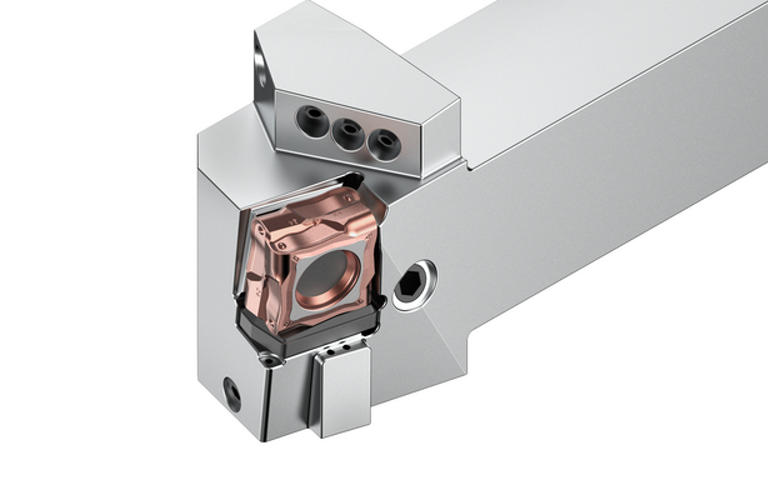
O FIX8 é a solução de torneamento para serviços pesados com oito arestas de corte por inserto.

Ideal para usinagem média e pesada com o menor custo por aresta.

Um sistema de fixação exclusivo puxa a pastilha para o encaixe, permitindo que ela resista a grandes forças de corte e vibrações. Grande profundidade de corte (até 12 mm) e capacidade de avanço (até 1,4 mm) garantem as mais altas taxas possíveis de remoção de material em aço, ferro fundido e aço inoxidável.

Com 15% menos forças de corte, o FIX8 também é adequado para tornos de baixa potência.

O design tangencial aumenta o contato do metal duro entre a peça de e o porta-ferramenta, permitindo que o sistema suporte cargas mais altas. Um calço de metal duro protege o encaixe contra deformação e garante a segurança do processo.
Selecionar filtros
Filtros
Exibir filtros em
Métrico
Polegada
keyFilters
Workpiece Material
Workpiece Material
  • P Steel (52)
    • P0
      Low-Carbon Steels, Long Chipping C < .25%; <125 HB; <530 N/mm^2 UTS (52)
    • P1
      Low-Carbon Steels, Short Chipping C < .25%; <125 HB; <530 N/mm^2 UTS (52)
    • P2
      Medium and High Carbon Steels C < .25%; <220 HB; <25 HRC; >530 N/mm^2 UTS (52)
    • P3
      Alloy Steels & Tool Steels C > .25%; <330 HB; <35 HRC; 600-850 N/mm^2 UTS (52)
    • P4
      Alloy Steels & Tool Steels C > .25%; 350-420 HB; 35-43 HRC; 850-1400 N/mm^2 UTS (52)
    • P5
      Ferritic, Martensitic, and PH Stainless Steels <330 HB; <35 HRC; 600-900 N/mm^2 UTS (52)
    • P6
      High Strength Ferritic, Martensitic, and PH Stainless Steels 350-450 HB; 35-43 HRC; 900-2400 N/mm^2 UTS (52)
  • M Stainless Steel (48)
    • M1
      Austenitic Stainless Steel 130-200 HB; <600 N/mm^2 UTS (48)
    • M2
      High Strength Austenitic Stainless and Cast Stainless Steels 150-230 HB; <25 HRC; >600 N/mm^2 UTS (48)
    • M3
      Duplex Stainless Steel 135-275 HB; <30 HRC; 500-1200 N/mm^2 UTS (48)
  • K Cast Iron (52)
    • K1
      Gray Cast Iron 120-290 HB; <32 HRC; 125-500 N/mm^2 UTS (52)
    • K2
      Low and Medium Strength CGI and Ductile Irons 130-260 HB; <28 HRC; <600 N/mm^2 UTS (52)
    • K3
      High Strength Ductile and Austempered Ductile Iron 180-350 HB; <43 HRC; >600 N/mm^2 UTS (52)
Applications
Applications
  • Chamfer Turning Chamfer Turning (48)
  • Facing Facing (34)
  • Turning Turning (52)
Cutting Condition
Cutting Condition
  • Heavily Interrupted Cut (52)
  • Lightly Interrupted Cut (52)
  • Smooth Cut (52)
  • Varying Depth of Cut (52)
Tool Cutting Edge Angle
  • 75.0 (20)
  • 91.0 (4)
  • 93.0 (24)
Tool Cutting Edge Angle Min a Tool Cutting Edge Angle Max
Connection Style
Connection Style
  • KM (12)
  • PSC (12)
  • Toolholder (24)
Internal Coolant Capability
Over All Length [L]
Over All Length [L]
  • 2.362 in (12)
  • 2.559 in (4)
  • 2.757 in (4)
  • 3.15 in (4)
  • 5.906 in (2)
  • 6.0 in (8)
  • 6.694 in (4)
  • 6.791 in (2)
  • 7.0 in (4)
  • 7.875 in (2)
  • 7.972 in (2)
Over All Length [L] Min a Over All Length [L] Max
Over All Length [L]
Over All Length [L]
  • 60.0 mm (12)
  • 65.0 mm (4)
  • 70.0 mm (4)
  • 80.0 mm (4)
  • 150.0 mm (2)
  • 152.4 mm (8)
  • 170.0 mm (4)
  • 172.5 mm (2)
  • 177.8 mm (4)
  • 200.0 mm (2)
  • 202.5 mm (2)
Over All Length [L] Min a Over All Length [L] Max
cornerConfiguration
Corner Radius
Corner Radius
  • 0.063 in (50)
  • 0.095 in (50)
Corner Radius Min a Corner Radius Max
Corner Radius
Corner Radius
  • 1.6 mm (50)
  • 2.401 mm (50)
Corner Radius Min a Corner Radius Max
Corner Chamfer
Corner Chamfer
  • 0.0 mm (4)
Corner Chamfer Min a Corner Chamfer Max
Corner Chamfer
Corner Chamfer
  • 0.0 in (4)
Corner Chamfer Min a Corner Chamfer Max
application
Minimum Depth of Cut
Minimum Feed
Minimum Feed
Grade Of Cutting Tool
  • KCP10B (48)
  • KCP25B (52)
  • KCP40B (48)
  • KCPK05 (48)
Hand Of Tool
Hand Of Tool
  • L (24)
  • R (24)
F Dimension
F Dimension
  • 20.55 mm (2)
  • 22.0 mm (2)
  • 25.151 mm (2)
  • 27.0 mm (4)
  • 27.25 mm (2)
  • 30.125 mm (2)
  • 31.75 mm (2)
  • 32.25 mm (2)
  • 35.0 mm (8)
  • 35.25 mm (2)
  • 38.1 mm (2)
  • 40.1 mm (2)
  • 40.25 mm (4)
  • 43.0 mm (2)
  • 45.0 mm (2)
  • 50.25 mm (2)
  • 50.801 mm (2)
  • 53.0 mm (2)
  • 55.0 mm (2)
F Dimension Min a F Dimension Max
F Dimension
F Dimension
  • 0.809 in (2)
  • 0.866 in (2)
  • 0.99 in (2)
  • 1.063 in (4)
  • 1.073 in (2)
  • 1.186 in (2)
  • 1.25 in (2)
  • 1.27 in (2)
  • 1.379 in (8)
  • 1.389 in (2)
  • 1.5 in (2)
  • 1.579 in (2)
  • 1.585 in (4)
  • 1.693 in (2)
  • 1.772 in (2)
  • 1.978 in (2)
  • 2.0 in (2)
  • 2.087 in (2)
  • 2.165 in (2)
F Dimension Min a F Dimension Max
Minimum Axial Groove Diameter
  • 850.0 mm (6)
  • 2000.0 mm (8)
Minimum Axial Groove Diameter Min a Minimum Axial Groove Diameter Max
Minimum Axial Groove Diameter
  • 33.465 in (6)
  • 78.74 in (8)
Minimum Axial Groove Diameter Min a Minimum Axial Groove Diameter Max
Cutting Direction
Cutting Direction
  • S (48)
Rake Angle Style
Rake Angle Style
  • DOUBLE NEGATIVE (48)
frontEnd
Clamp Style
Clamp Style
  • P (40)
  • X (4)
Insert Shape
Insert Shape
  • C-DIAMOND/RHOMBIC 80 (4)
  • FIX-PERFECT 8 CUT EDGES (48)
insertGeometry
Shape
Shape
  • FIX-PERFECT 8 CUT EDGES (4)
Insert IC Size
Insert IC Size
  • 19.05 mm (4)
Insert IC Size Min a Insert IC Size Max
Insert IC Size
Insert IC Size
  • 0.75 in (4)
Insert IC Size Min a Insert IC Size Max
Cutting Edge Length
Cutting Edge Length
  • 12.0 mm (4)
Cutting Edge Length Min a Cutting Edge Length Max
Cutting Edge Length
Cutting Edge Length
  • 0.473 in (4)
Cutting Edge Length Min a Cutting Edge Length Max
Chip Breaker CBMD
Chip Breaker CBMD
  • RN (4)
Tolerance Class
Tolerance Class
  • U (4)
backEnd
Connection Type
Connection Type
  • SQUARE SHANK (24)
  • TAPER SHANK (24)
System Size
System Size
  • KM50TS (4)
  • KM63TS (4)
  • KM80TS (4)
  • PSC50 (4)
  • PSC63 (4)
  • PSC80 (4)
Back-End Diameter
Back-End Diameter
  • 50.0 mm (8)
  • 63.0 mm (8)
  • 80.0 mm (8)
Back-End Diameter Min a Back-End Diameter Max
Back-End Diameter
Back-End Diameter
  • 1.969 in (8)
  • 2.48 in (8)
  • 3.15 in (8)
Back-End Diameter Min a Back-End Diameter Max
Shank Height
Shank Height
  • 0.984 in (2)
  • 1.0 in (2)
  • 1.25 in (6)
  • 1.26 in (6)
  • 1.5 in (4)
  • 1.575 in (4)
Shank Height Min a Shank Height Max
Shank Height
Shank Height
  • 25.0 mm (2)
  • 25.401 mm (2)
  • 31.75 mm (6)
  • 32.0 mm (6)
  • 38.1 mm (4)
  • 40.0 mm (4)
Shank Height Min a Shank Height Max
Shank Width
Shank Width
  • 0.984 in (2)
  • 1.0 in (2)
  • 1.25 in (6)
  • 1.26 in (6)
  • 1.5 in (4)
  • 1.575 in (4)
Shank Width Min a Shank Width Max
Shank Width
Shank Width
  • 25.0 mm (2)
  • 25.401 mm (2)
  • 31.75 mm (6)
  • 32.0 mm (6)
  • 38.1 mm (4)
  • 40.0 mm (4)
Shank Width Min a Shank Width Max
No filters matching ""
Você está prestes a adicionar à sua página Minhas soluções. Deseja continuar?
product-image
Please adjust the following properties from

Código de catálogo ISO

Número do catálogo ANSI

to find similar products.

The following files are available

Please select a file to download

Models

Product data

Você deve ser registrado para ver as informações do seu painel
Session expired due to inactivity, please login again
Os produtos () que você estava tentando adicionar ao carrinho não estão disponíveis, Entrar em contato com o atendimento ao cliente
itens adicionados com sucesso ao carrinho
Ver o carrinho

. Please enter the desired qty for the material(s) you want to include in your promotion or Proceed Without Promotion and only your base materials will be added to the cart.

Minimum quantity should be

SAP Material Number Código de catálogo ISO Classe    
Thank you for your registration, pending approval & completion of the registration, your access is currently limited. Full utilization of product search capabilities & collaboration space is available and will remain. Please allow 2 business days for registration completion.

You are about to leave the Solution building process.

Are you sure you want to leave?