List Price
/each
Discount
Your Price
/each
Sold in pkg. of 0Adjusted to meet the minimum package size.
Minimum qty: 0Adjusted to meet the minimum quantity requirement.
In StockThis item is no longer availableLonger Delivery


 +1
+1

 100055043
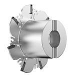
 Slotting: Side
 Side Milling/Shoulder Milling: Bottom Shouldering
Downloaded file will be available after import in the {{cadTool}} tool library.
| Material Number | 5614853 |
| ISO Catalog ID | KNSM100R07X21S022 |
| ANSI Catalog ID | KNSM100R07X21S022 |
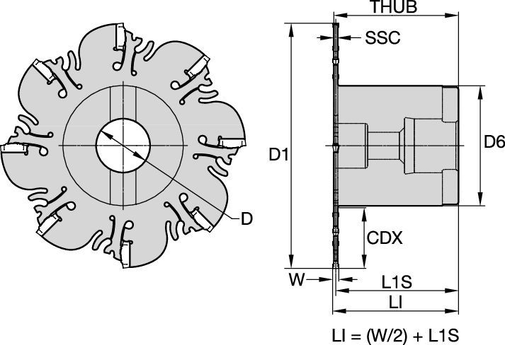
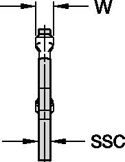
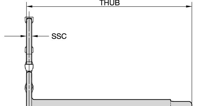
| Insert Size [SSC] | 21 |
| [BM] Cutting Width Minimum | 2.5 mm |
| [BM] Cutting Width Minimum | 0.098 in |
| [BMAX] Cutting Width Maximum | 3.2 mm |
| [BMAX] Cutting Width Maximum | 0.126 in |
| [D1] Effective Cutting Diameter | 100 mm |
| [D1] Effective Cutting Diameter | 3.937 in |
| [D] Adapter / Shank / Bore Diameter | 22 mm |
| [D] Adapter / Shank / Bore Diameter | 0.87 in |
| [D6] Hub Diameter | 49 mm |
| [D6] Hub Diameter | 1.929 in |
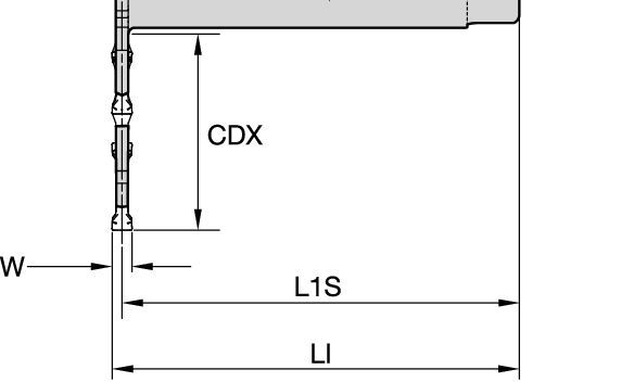
| [CDX] Radial Maximum Depth of Cut | 24.7 mm |
| [CDX] Radial Maximum Depth of Cut | 0.972 in |
| [L1] Gage Length | 51.05 mm |
| [L1] Gage Length | 2.0772 in |
| [L1S] Secondary Gage Length | 50 mm |
| [L1S] Secondary Gage Length | 1.969 in |
| [W1] Blade Width | 2.1 mm |
| [W1] Blade Width | 0.083 in |
| [THUB] Hub Thickness | 51.05 mm |
| [THUB] Hub Thickness | 2.01 in |
| Number of Inserts | 7 |
| Gage Insert | XCP21_____ |
| Weight Kilograms | 0.75 |
| Max RPM | 800 |
100055043Slotting: SideSide Milling/Shoulder Milling: Bottom ShoulderingCreate Solution to calculate Feeds and Speeds
After creating a solution just choose the Feeds & Speeds icon and our system will provide recommendations. You can customize the information by adding your machine and specifications or make adjustments using the sliders.
| KNS® Slotting Cutter • Recommended Starting Feeds [mm/th] | ||||||||||||
| Insert Geometry | Recommended Starting Feed per Tooth (Fz) in Relation to % of Radial Engagement (ae) | |||||||||||
| 5% | 10% | 20% | 30–100% | |||||||||
| L | M | H | L | M | H | L | M | H | L | M | H | |
| .S..GP | 0,13 | 0,28 | 0,35 | 0,09 | 0,20 | 0,32 | 0,07 | 0,15 | 0,32 | 0,06 | 0,12 | 0,30 |
| L = Light Machining; M = Medium Machining; H = Heavy Machining NOTE: Use "Light Machining" values as starting feed rate. | ||||||||||||
| KNS® Slotting Cutter • Recommended Starting Feeds [IPT] | ||||||||||||
| Insert Geometry | Recommended Starting Feed per Tooth (Fz) in Relation to % of Radial Engagement (ae) | |||||||||||
| 5% | 10% | 20% | 30–100% | |||||||||
| L | M | H | L | M | H | L | M | H | L | M | H | |
| .S..GP | 0.005 | 0.011 | 0.027 | 0.004 | 0.008 | 0.020 | 0.003 | 0.006 | 0.015 | 0.002 | 0.005 | 0.012 |
| L = Light Machining; M = Medium Machining; H = Heavy Machining NOTE: Use "Light Machining" values as starting feed rate. | ||||||||||||
| KNS® Slotting Cutter • Recommended Starting Speed [m/min] | ||||||||||
| Grade | KCU25 | KCPK30 | KMF | |||||||
| Chip Thickness hex mm | Min | Max | Min | Max | Min | Max | ||||
| Material Group | Max | Start | Min | Max | Start | Min | Max | Start | Min | |
| P | 1 | 260 | 230 | 215 | 455 | 395 | 370 | 295 | 260 | 245 |
| 2 | 220 | 190 | 160 | 280 | 255 | 230 | 250 | 215 | 180 | |
| 3 | 200 | 170 | 140 | 255 | 230 | 205 | 230 | 195 | 160 | |
| 4 | 180 | 150 | 120 | 225 | 185 | 160 | 205 | 170 | 135 | |
| 5 | 150 | 135 | 120 | 190 | 170 | 150 | 170 | 155 | 135 | |
| 6 | 130 | 100 | 80 | 160 | 135 | 110 | 150 | 115 | 90 | |
| M | 1 | 210 | 170 | 135 | 205 | 185 | 155 | 195 | 170 | 155 |
| 2 | 170 | 150 | 110 | 185 | 160 | 140 | 175 | 150 | 125 | |
| 3 | 130 | 120 | 85 | 145 | 130 | 115 | 130 | 115 | 90 | |
| K | 1 | 270 | 220 | 170 | 295 | 265 | 240 | – | – | – |
| 2 | 230 | 190 | 160 | 235 | 210 | 190 | – | – | – | |
| 3 | 210 | 160 | 140 | 195 | 175 | 160 | – | – | – | |
| N | 1 | – | – | – | – | – | – | – | – | – |
| 2 | – | – | – | – | – | – | – | – | – | |
| 3 | – | – | – | – | – | – | – | – | – | |
| S | 1 | 30 | 25 | 20 | – | – | – | 40 | 35 | 30 |
| 2 | 30 | 25 | 20 | – | – | – | 40 | 35 | 30 | |
| 3 | 40 | 30 | 20 | – | – | – | 50 | 40 | 30 | |
| 4 | 55 | 40 | 25 | 50 | 45 | 35 | 55 | 50 | 35 | |
| H | 1 | – | – | – | – | – | – | – | – | – |
| Recommended Starting Speed are pointing to 90° Shoulder Milling . Starting Speed for Face and Copy Milling can be Increased by 20 %. As the average chip thickness increases, speed should be decreased. Material groups P, M, K and H show recommended starting speeds for dry machining. For wet machining, reduce speed by 20%. Material groups N and S show recommended starting speeds for wet machining. Not recommended for dry machining. | ||||||||||
| KNS® Slotting Cutter • Recommended Starting Speed [SFM] | ||||||||||
| Grade | KCPK30 | KCPK30 | KMF | |||||||
| Chip Thickness hex Inch | Min | Max | Min | Max | Min | Max | ||||
| Material Group | Max | Start | Min | Max | Start | Min | Max | Start | Min | |
| P | 1 | 855 | 755 | 705 | 1495 | 1295 | 1215 | 970 | 855 | 805 |
| 2 | 720 | 625 | 525 | 920 | 835 | 755 | 820 | 705 | 590 | |
| 3 | 655 | 560 | 460 | 835 | 755 | 675 | 755 | 640 | 525 | |
| 4 | 590 | 490 | 395 | 740 | 605 | 525 | 675 | 560 | 445 | |
| 5 | 490 | 445 | 395 | 625 | 560 | 490 | 560 | 510 | 445 | |
| 6 | 425 | 330 | 260 | 525 | 445 | 360 | 490 | 375 | 295 | |
| M | 1 | 690 | 560 | 445 | 675 | 605 | 510 | 640 | 560 | 510 |
| 2 | 560 | 490 | 360 | 605 | 525 | 460 | 575 | 490 | 410 | |
| 3 | 425 | 395 | 280 | 475 | 425 | 375 | 425 | 375 | 295 | |
| K | 1 | 885 | 720 | 560 | 970 | 870 | 785 | – | – | – |
| 2 | 755 | 625 | 525 | 770 | 690 | 625 | – | – | – | |
| 3 | 690 | 525 | 460 | 640 | 575 | 525 | – | – | – | |
| N | 1 | – | – | – | – | – | – | – | – | – |
| 2 | – | – | – | – | – | – | – | – | – | |
| 3 | – | – | – | – | – | – | – | – | – | |
| S | 1 | 100 | 80 | 65 | – | – | – | 130 | 115 | 100 |
| 2 | 100 | 80 | 65 | – | – | – | 130 | 115 | 100 | |
| 3 | 130 | 100 | 65 | – | – | – | 165 | 130 | 100 | |
| 4 | 180 | 130 | 80 | 165 | 150 | 115 | 180 | 165 | 115 | |
| H | 1 | – | – | – | – | – | – | – | – | – |
| Recommended Starting Speed are pointing to 90° Shoulder Milling . Starting Speed for Face and Copy Milling can be Increased by 20 %. As the average chip thickness increases, speed should be decreased. Material groups P, M, K and H show recommended starting speeds for dry machining. For wet machining, reduce speed by 20%. Material groups N and S show recommended starting speeds for wet machining. Not recommended for dry machining. | ||||||||||
| KNS® Slotting Cutter • Insert Selection Guide | ||||||
| Material Group | Light | General | Heavy | |||
| – | (Light geometry) | (Strong geometry) | ||||
| – | wear |  | toughness | |||
| – | Geometry | Grade | Geometry | Grade | Geometry | Grade |
| P1-P2 | .S..GP | KCU25 | .S..GP | KCU25 | .S..GP | KCPM40 |
| P3-P4 | .S..GP | KCU25 | .S..GP | KCU25 | .S..GP | KCPM40 |
| P5-P6 | .S..GP | KCU25 | .S..GP | KCU25 | .S..GP | KCPM40 |
| M1-M2 | .S..GP | KCU25 | .S..GP | KCPM40 | .S..GP | KCPM40 |
| M3 | .S..GP | KCU25 | .S..GP | KCPM40 | .S..GP | KCPM40 |
| K1-K2 | .S..GP | KCU25 | .S..GP | KCPK30 | .S..GP | KCPK30 |
| K3 | .S..GP | KCU25 | .S..GP | KCPK30 | .S..GP | KCPK30 |
| N1-N2 | – | – | .S..GP | KCU25 | – | – |
| N3 | – | – | .S..GP | KCU25 | – | – |
| S1-S2 | .S..GP | KCU25 | .S..GP | KCU25 | .S..GP | KCU25 |
| S3 | .S..GP | KCU25 | .S..GP | KCU25 | .S..GP | KCU25 |
| S4 | .S..GP | KCU25 | .S..GP | KCU25 | .S..GP | KCU25 |
| H1 | – | – | – | – | – | – |
I have read and accepted the Terms & Conditions of use


ISO Catalog Number
ANSI Catalog Number
to find similar products.Please select a file to download
Models
Product data
. Please enter the desired qty for the material(s) you want to include in your promotion or Proceed Without Promotion and only your base materials will be added to the cart.
Minimum quantity should be
| SAP Material Number | ISO Catalog Number | Grade |
|---|
You are about to leave the Solution building process.
Are you sure you want to leave?