Producto similar a:
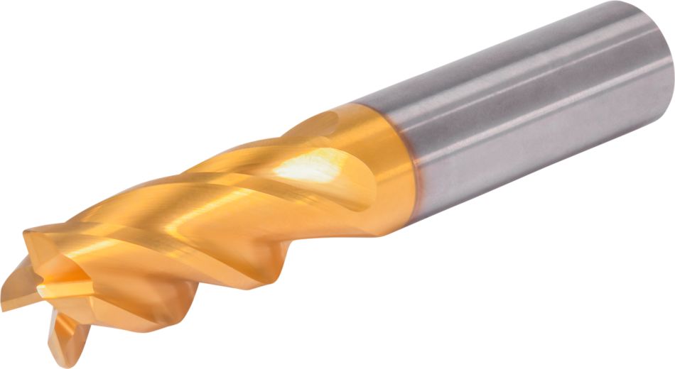
GOmill™ PRO • Chamfered • 4 Flutes • Necked • Weldon Shank • Metric
Solid Carbide End Mill for Roughing and Finishing of Multiple Materials
Número de material7231191
Referencia ISOGOPR4CH1600N032HBMReferencia ANSIGOPR4CH1600N032HBM
- P Acero
- M Acero inoxidable
- K Fundición
- N Materiales no ferrosos
- S Aleaciones de alta temperatura
- H Materiales endurecidos
Fresado helicoidal
Rectificado en rampa: Material en bruto
Ranurado: Placa cuadrada
Fresado lateral/Fresado en escuadra: Placa cuadrada
Mango — Weldon cilíndrico
Estilo de esquina: Bisel en esquina
Sending to {{cadTool}} in progress...
Downloaded file will be available after import in the {{cadTool}} tool library.
- Información general
- Datos de aplicación
- Descargas
- Piezas compatibles Lado máquina
- Comentarios
- Preguntas y Respuestas

| Número de material | 7231191 |
| Referencia ISO | GOPR4CH1600N032HBM |
| Referencia ANSI | GOPR4CH1600N032HBM |
| Calidad | KCU20 |
| Tipo de adaptador Lateral de máquina | Weldon |
| Diámetro de corte efectivo [D1] | 16 mm |
| Diámetro de corte efectivo [D1] | 0.6299 in |
| Diámetro de cuello [D3] | 15.04 mm |
| Diámetro de cuello [D3] | 0.5921 in |
| Adaptador/Mango/Diá int [D] | 16 mm |
| Adaptador/Mango/Diá int [D] | 0.6299 in |
| 1.ª profundidad de corte máxima [AP1MAX] | 32 mm |
| 1.ª profundidad de corte máxima [AP1MAX] | 1.2598 in |
| Longitud utilizable [L3] | 44 mm |
| Longitud utilizable [L3] | 1.7323 in |
| Longitud total [L] | 92 mm |
| Longitud total [L] | 3.622 in |
| Ancho bisel esquina [BCH] | 0.35 mm |
| Ancho bisel esquina [BCH] | 0.0138 in |
| Número de canales [Z] | 4 |
Materiales de la pieza de trabajo
- Acero
- Acero inoxidable
- Fundición
- Materiales no ferrosos
- Aleaciones de alta temperatura
- Materiales endurecidos
Uses and application
Fresado helicoidal
Rectificado en rampa: Material en bruto
Ranurado: Placa cuadrada
Fresado lateral/Fresado en escuadra: Placa cuadrada
Mango — Weldon cilíndrico
Estilo de esquina: Bisel en esquina
Features and benefits
- Asymmetric divided flute and variable helix angle for better vibration control and tool life.
- Multilayer TiN/TiALN coating for high performance at medium-high cutting on steels, stainless steels and cast iron.
- Ideal for shops working in the general engineering, transportation, energy and medical industries.
- Designed for side and shoulder milling, helical milling, pocketing, slotting and ramping.
Crear una solución para calcular la velocidad y el avance
Después de crear una solución, sólo tiene que elegir el icono Avance y Velocidad y nuestro sistema le ofrecerá recomendaciones. Puede personalizar la información añadiendo su máquina y especificaciones o realizar ajustes utilizando los controles deslizantes.
Datos de aplicación
| Adjustment factors for speed (Vc) and feed (Fz) • Metric | |||||||||||
| Ae/D1 | 2% | 4% | 5% | 8% | 10% | 12% | 20% | 30% | 40% | 50% | 100% |
| Kv | 2.1 - 3.6 | 1.6 - 3 | 1.6 - 2.5 | 1.6 | 1.4 | 1.38 | 1.3 | 1.2 | 1.1 | 1 | 1 |
| KFz | 3.58 | 2.56 | 2.3 | 1.84 | 1.67 | 1.54 | 1.25 | 1.09 | 1.02 | 1 | 0.9 |
| Note: Identify the radial engagement per percentage of the tool diameter (Ae/D1). That column will give you the factor to multiply the Base SMF and Base IPT on the Speed and Feed original table Kv = Factor to multiply the Speed by KFz = Factor to multiply the Feed by | |||||||||||
| To calculate application specific cutting data, please use Kv coefficient, and KFz from tables for adaption of cutting speeds and feeds respectively: Vc new = Vc * Kv IPT new = IPT * KFz | Sample Calculation Material: P5 D1: 14.0 mm Ae: 20% of D1 Recommended Speed Vc : 80 m/min Recommended Feed Fz: 0.063 mm/th Adjustment coefficient Kv : 1.30 Adjustment coefficient KFz : 1.25 | Final cutting data recommendation: Vc new = 80 * 1.30 = 104 m/min Fz new = 0.063 * 1.30 = 0.079 mm/th | |||||||||
| GOmill™ PRO • Regular • Recommended Starting Speed and Feed [Metric] | ||||||||||||||||||||
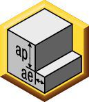 | 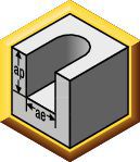 |  | ||||||||||||||||||
| KCU25 | Avance por diente recomendado (fz = mm/diente) para fresado lateral (A). Para ranurado (B), reduzca el valor de fz en un 20%. | |||||||||||||||||||
| Fresado lateral | Ranurado | Velocidad de corte | D1 | |||||||||||||||||
| Grupo de materiales | ap | ae | ap | Mín | Inicio | Máx. | mm | 2,0 | 3,0 | 4,0 | 5,0 | 6,0 | 8,0 | 10,0 | 12,0 | 14,0 | 16,0 | 18,0 | 20,0 | 25,0 |
| P0 | Ap1 Max | 0,4 x D1 | 1,0 x D1 | 150 | 175 | 200 | fz | 0.014 | 0.021 | 0.028 | 0.036 | 0.044 | 0.060 | 0.072 | 0.083 | 0.092 | 0.101 | 0.108 | 0.114 | 0.124 |
| P1 | Ap1 Max | 0,4 x D1 | 1,0 x D1 | 150 | 175 | 200 | fz | 0.014 | 0.021 | 0.028 | 0.036 | 0.044 | 0.060 | 0.072 | 0.083 | 0.092 | 0.101 | 0.108 | 0.114 | 0.124 |
| P2 | Ap1 Max | 0,4 x D1 | 1,0 x D1 | 140 | 165 | 190 | fz | 0.014 | 0.021 | 0.028 | 0.036 | 0.044 | 0.060 | 0.072 | 0.083 | 0.092 | 0.101 | 0.108 | 0.114 | 0.124 |
| P3 | Ap1 Max | 0,4 x D1 | 1,0 x D1 | 120 | 140 | 160 | fz | 0.011 | 0.017 | 0.023 | 0.030 | 0.036 | 0.050 | 0.061 | 0.070 | 0.079 | 0.087 | 0.095 | 0.101 | 0.114 |
| P4 | Ap1 Max | 0,4 x D1 | 0,75 x D1 | 90 | 120 | 150 | fz | 0.010 | 0.016 | 0.021 | 0.027 | 0.033 | 0.045 | 0.054 | 0.062 | 0.070 | 0.077 | 0.083 | 0.088 | 0.098 |
| P5 | Ap1 Max | 0,4 x D1 | 1,0 x D1 | 60 | 80 | 100 | fz | 0.009 | 0.014 | 0.019 | 0.024 | 0.029 | 0.040 | 0.048 | 0.056 | 0.063 | 0.070 | 0.076 | 0.081 | 0.091 |
| P6 | Ap1 Max | 0,4 x D1 | 0,75 x D1 | 50 | 63 | 75 | fz | 0.008 | 0.012 | 0.016 | 0.020 | 0.025 | 0.034 | 0.040 | 0.047 | 0.052 | 0.057 | 0.061 | 0.065 | 0.071 |
| M1 | Ap1 Max | 0,4 x D1 | 1,0 x D1 | 90 | 103 | 115 | fz | 0.011 | 0.017 | 0.023 | 0.030 | 0.036 | 0.050 | 0.061 | 0.070 | 0.079 | 0.087 | 0.095 | 0.101 | 0.114 |
| M2 | Ap1 Max | 0,4 x D1 | 1,0 x D1 | 60 | 70 | 80 | fz | 0.009 | 0.014 | 0.019 | 0.024 | 0.029 | 0.040 | 0.048 | 0.056 | 0.063 | 0.070 | 0.076 | 0.081 | 0.091 |
| M3 | Ap1 Max | 0,4 x D1 | 1,0 x D1 | 60 | 65 | 70 | fz | 0.008 | 0.012 | 0.016 | 0.020 | 0.025 | 0.034 | 0.040 | 0.047 | 0.052 | 0.057 | 0.061 | 0.065 | 0.071 |
| K1 | Ap1 Max | 0,4 x D1 | 1,0 x D1 | 120 | 135 | 150 | fz | 0.014 | 0.021 | 0.028 | 0.036 | 0.044 | 0.060 | 0.072 | 0.083 | 0.092 | 0.101 | 0.108 | 0.114 | 0.124 |
| K2 | Ap1 Max | 0,4 x D1 | 1,0 x D1 | 110 | 125 | 140 | fz | 0.011 | 0.017 | 0.023 | 0.030 | 0.036 | 0.050 | 0.061 | 0.070 | 0.079 | 0.087 | 0.095 | 0.101 | 0.114 |
| K3 | Ap1 Max | 0,4 x D1 | 1,0 x D1 | 110 | 120 | 130 | fz | 0.009 | 0.014 | 0.019 | 0.024 | 0.029 | 0.040 | 0.048 | 0.056 | 0.063 | 0.070 | 0.076 | 0.081 | 0.091 |
| S1 | Ap1 Max | 0,4 x D1 | 0,3 x D1 | 50 | 70 | 90 | fz | 0.011 | 0.017 | 0.023 | 0.030 | 0.036 | 0.050 | 0.061 | 0.070 | 0.079 | 0.087 | 0.095 | 0.101 | 0.114 |
| S2 | Ap1 Max | 0,4 x D1 | 0,3 x D1 | 25 | 38 | 50 | fz | 0.006 | 0.009 | 0.013 | 0.016 | 0.019 | 0.026 | 0.032 | 0.037 | 0.042 | 0.046 | 0.050 | 0.054 | 0.061 |
| S3 | Ap1 Max | 0,4 x D1 | 1,0 x D1 | 25 | 33 | 40 | fz | 0.006 | 0.009 | 0.013 | 0.016 | 0.019 | 0.026 | 0.032 | 0.037 | 0.042 | 0.046 | 0.050 | 0.054 | 0.061 |
| S4 | Ap1 Max | 0,4 x D1 | 1,0 x D1 | 50 | 55 | 60 | fz | 0.007 | 0.011 | 0.016 | 0.021 | 0.026 | 0.037 | 0.045 | 0.052 | 0.058 | 0.064 | 0.069 | 0.074 | 0.084 |
| H1 | Ap1 Max | 0,4 x D1 | 0,75 x D1 | 80 | 110 | 140 | fz | 0.010 | 0.016 | 0.021 | 0.027 | 0.033 | 0.045 | 0.054 | 0.062 | 0.070 | 0.077 | 0.083 | 0.088 | 0.098 |
| H2 | Ap1 Max | 0,4 x D1 | 0,5 x D1 | 70 | 95 | 120 | fz | 0.008 | 0.012 | 0.016 | 0.020 | 0.025 | 0.034 | 0.040 | 0.047 | 0.052 | 0.057 | 0.061 | 0.065 | 0.071 |
| Lower value of cuting speed is used for high stock removal applications or for higher hardness (machinability) within group. Higher value of cuting speed is used for finishing applications or for lower hardness (machinability) within group. Above parameters are based on ideal conditions. For smaller taper machining centers, please adjust parameters accordiongly on diameters greater than 12mm. For better surface finish reduce feed per tooth. Side and Slotting milling aplications: for longest reach (L3) tools, reduce Ae by 30%. Sharp corner tools not recommended for sloting aplication. | ||||||||||||||||||||
| Adjustment factors for speed (Vc) and feed (Fz) • Metric | |||||||||||
| Ae/D1 | 2% | 4% | 5% | 8% | 10% | 12% | 20% | 30% | 40% | 50% | 100% |
| Kv | 2.1 - 3.6 | 1.6 - 3 | 1.6 - 2.5 | 1.6 | 1.4 | 1.38 | 1.3 | 1.2 | 1.1 | 1 | 1 |
| KFz | 3.58 | 2.56 | 2.3 | 1.84 | 1.67 | 1.54 | 1.25 | 1.09 | 1.02 | 1 | 0.9 |
| Note: Identify the radial engagement per percentage of the tool diameter (Ae/D1). That column will give you the factor to multiply the Base SMF and Base IPT on the Speed and Feed original table Kv = Factor to multiply the Speed by KFz = Factor to multiply the Feed by | |||||||||||
| To calculate application specific cutting data, please use Kv coefficient, and KFz from tables for adaption of cutting speeds and feeds respectively: Vc new = Vc * Kv IPT new = IPT * KFz | Sample Calculation Material: P5 D1: 14.0 mm Ae: 20% of D1 Recommended Speed Vc : 80 m/min Recommended Feed Fz: 0.063 mm/th Adjustment coefficient Kv : 1.30 Adjustment coefficient KFz : 1.25 | Final cutting data recommendation: Vc new = 80 * 1.30 = 104 m/min Fz new = 0.063 * 1.30 = 0.079 mm/th | |||||||||
| GOmill™ PRO • Long • Recommended Starting Speed and Feed [Metric] | ||||||||||||||||||
 |  | |||||||||||||||||
| KCU25 | Avance por diente recomendado (fz = mm/diente) para fresado lateral (A). Para ranurado (B), reduzca el valor de fz en un 20%. | |||||||||||||||||
| Fresado lateral | Velocidad de corte | D1 | ||||||||||||||||
| Grupo de materiales | ap | ae | Mín | Inicio | Máx. | mm | 2,0 | 3,0 | 4,0 | 5,0 | 6,0 | 8,0 | 10,0 | 12,0 | 14,0 | 18,0 | 20,0 | 25,0 |
| P0 | Ap1 Max | 0.2xD | 150 | 175 | 200 | fz | 0.014 | 0.021 | 0.028 | 0.036 | 0.044 | 0.060 | 0.072 | 0.083 | 0.092 | 0.108 | 0.114 | 0.124 |
| P1 | Ap1 Max | 0.2xD | 150 | 175 | 200 | fz | 0.014 | 0.021 | 0.028 | 0.036 | 0.044 | 0.060 | 0.072 | 0.083 | 0.092 | 0.108 | 0.114 | 0.124 |
| P2 | Ap1 Max | 0.2xD | 140 | 165 | 190 | fz | 0.014 | 0.021 | 0.028 | 0.036 | 0.044 | 0.060 | 0.072 | 0.083 | 0.092 | 0.108 | 0.114 | 0.124 |
| P3 | Ap1 Max | 0.2xD | 120 | 140 | 160 | fz | 0.011 | 0.017 | 0.023 | 0.030 | 0.036 | 0.050 | 0.061 | 0.070 | 0.079 | 0.095 | 0.101 | 0.114 |
| P4 | Ap1 Max | 0.2xD | 90 | 120 | 150 | fz | 0.010 | 0.016 | 0.021 | 0.027 | 0.033 | 0.045 | 0.054 | 0.062 | 0.070 | 0.083 | 0.088 | 0.098 |
| P5 | Ap1 Max | 0.2xD | 60 | 80 | 100 | fz | 0.009 | 0.014 | 0.019 | 0.024 | 0.029 | 0.040 | 0.048 | 0.056 | 0.063 | 0.076 | 0.081 | 0.091 |
| P6 | Ap1 Max | 0.15xD | 50 | 63 | 75 | fz | 0.008 | 0.012 | 0.016 | 0.020 | 0.025 | 0.034 | 0.040 | 0.047 | 0.052 | 0.061 | 0.065 | 0.071 |
| M1 | Ap1 Max | 0.2xD | 90 | 103 | 115 | fz | 0.011 | 0.017 | 0.023 | 0.030 | 0.036 | 0.050 | 0.061 | 0.070 | 0.079 | 0.095 | 0.101 | 0.114 |
| M2 | Ap1 Max | 0.2xD | 60 | 70 | 80 | fz | 0.009 | 0.014 | 0.019 | 0.024 | 0.029 | 0.040 | 0.048 | 0.056 | 0.063 | 0.076 | 0.081 | 0.091 |
| M3 | Ap1 Max | 0.2xD | 60 | 65 | 70 | fz | 0.008 | 0.012 | 0.016 | 0.020 | 0.025 | 0.034 | 0.040 | 0.047 | 0.052 | 0.061 | 0.065 | 0.071 |
| K1 | Ap1 Max | 0.2xD | 120 | 135 | 150 | fz | 0.014 | 0.021 | 0.028 | 0.036 | 0.044 | 0.060 | 0.072 | 0.083 | 0.092 | 0.108 | 0.114 | 0.124 |
| K2 | Ap1 Max | 0.2xD | 110 | 125 | 140 | fz | 0.011 | 0.017 | 0.023 | 0.030 | 0.036 | 0.050 | 0.061 | 0.070 | 0.079 | 0.095 | 0.101 | 0.114 |
| K3 | Ap1 Max | 0.2xD | 110 | 120 | 130 | fz | 0.009 | 0.014 | 0.019 | 0.024 | 0.029 | 0.040 | 0.048 | 0.056 | 0.063 | 0.076 | 0.081 | 0.091 |
| S1 | Ap1 Max | 0.1xD | 50 | 70 | 90 | fz | 0.011 | 0.017 | 0.023 | 0.030 | 0.036 | 0.050 | 0.061 | 0.070 | 0.079 | 0.095 | 0.101 | 0.114 |
| S2 | Ap1 Max | 0.1xD | 25 | 38 | 50 | fz | 0.006 | 0.009 | 0.013 | 0.016 | 0.019 | 0.026 | 0.032 | 0.037 | 0.042 | 0.050 | 0.054 | 0.061 |
| S3 | Ap1 Max | 0.1xD | 25 | 33 | 40 | fz | 0.006 | 0.009 | 0.013 | 0.016 | 0.019 | 0.026 | 0.032 | 0.037 | 0.042 | 0.050 | 0.054 | 0.061 |
| S4 | Ap1 Max | 0.15xD | 50 | 55 | 60 | fz | 0.007 | 0.011 | 0.016 | 0.021 | 0.026 | 0.037 | 0.045 | 0.052 | 0.058 | 0.069 | 0.074 | 0.084 |
| H1 | Ap1 Max | 0.15xD | 80 | 110 | 140 | fz | 0.010 | 0.016 | 0.021 | 0.027 | 0.033 | 0.045 | 0.054 | 0.062 | 0.070 | 0.083 | 0.088 | 0.098 |
| H2 | Ap1 Max | 0.15xD | 70 | 95 | 120 | fz | 0.008 | 0.012 | 0.016 | 0.020 | 0.025 | 0.034 | 0.040 | 0.047 | 0.052 | 0.061 | 0.065 | 0.071 |
| Lower value of cuting speed is used for high stock removal applications or for higher hardness (machinability) within group. Higher value of cuting speed is used for finishing applications or for lower hardness (machinability) within group. Above parameters are based on ideal conditions. For smaller taper machining centers, please adjust parameters accordiongly on diameters greater than 12mm. For better surface finish reduce feed per tooth. Side milling aplications: for longest reach (L3) tools, reduce Ae by 30%. Sharp corner tools not recommended for sloting aplication. | ||||||||||||||||||
TechnicalInfo
| Angle of engagement (phi°) relative to cutting width (Ae) |  | ||||||||||
| ae | 2% | 5% | 7.50% | 10% | 15% | 20% | 30% | 40% | 50% | 100% | |
| phi - angle of engagement | 16.26 | 25.84 | 31.79 | 36.87 | 45.57 | 53.13 | 66.42 | 78.46 | 90 | 180 | |
I have read and accepted the Terms & Conditions of use
CAD Drawings Models
Can’t find the file type you’re looking for?
Product data

