Produit similaire à:
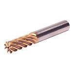
HARVI™ IV • Radiused • 8 Flutes • Internal Coolant • Chipbreaker • Plain Shank • Metric
HARVI™ IV Eight Flute End Mill for Roughing and Finishing
Covering the Broadest Range of Applications and Materials
Numéro de matériel7104273
Ref. ISO CatalogueHA4R8RA1200X048HAR200DMRef. ANSI CatalogueHA4R8RA1200X048HAR200DM
- P Acier
- M Acier inoxydable
- S Alliages hautes températures
- H Matériaux trempés
Trochoidal Milling
100665610
107038547
Fraisage hélicoïdal
Ramping : Ébauche
Fraisage de côté/avec épaulement : Bout plat
Usinage de poches
Sending to {{cadTool}} in progress...
Downloaded file will be available after import in the {{cadTool}} tool library.
| Numéro de matériel | 7104273 |
| Ref. ISO Catalogue | HA4R8RA1200X048HAR200DM |
| Ref. ANSI Catalogue | HA4R8RA1200X048HAR200DM |
| Nuance | KCSM15A |
| Style adaptateur du côté machine | Straight-Cylindrical |
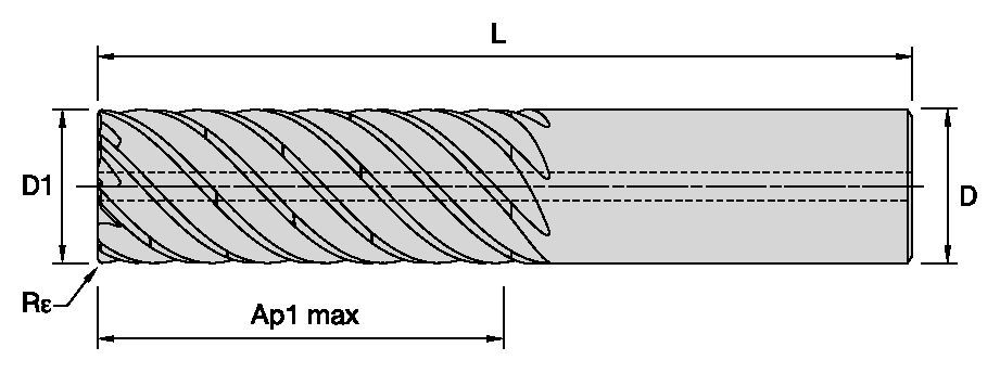
| [D1] Diamètre effectif de coupe | 12 mm |
| [D1] Diamètre effectif de coupe | 0.4724 in |
| [D] Adaptateur / Queue / Diamètre d’alésage | 12 mm |
| [D] Adaptateur / Queue / Diamètre d’alésage | 0.4724 in |
| [AP1MAX] 1re profondeur de coupe maximale | 48 mm |
| [AP1MAX] 1re profondeur de coupe maximale | 1.8898 in |
| [L3] Longueur exploitable | 53.44 mm |
| [L3] Longueur exploitable | 2.1039 in |
| [L] Longueur totale | 105 mm |
| [L] Longueur totale | 4.1339 in |
| [Re] Rayon de bec | 2 mm |
| [Re] Rayon de bec | 0.079 in |
| [Z] Nombre de goujures | 8 |
Matériaux de pièce à usiner
- Acier
- Acier inoxydable
- Alliages hautes températures
- Matériaux trempés
Uses and application
Trochoidal Milling
100665610
107038547
Fraisage hélicoïdal
Ramping : Ébauche
Fraisage de côté/avec épaulement : Bout plat
Usinage de poches
Features and benefits
- Single tool for roughing and finishing to reduce tool setups.
- Proprietary core and flute design with optimum flute spacing for perfect chip formation and highest tool rigidity.
- Developed for highest productivity in titanium, high-temperature alloys, and stainless steels.
- With chip breakers for optimized chip evacuation.
Créez une Solution pour calculer les avances et vitesses
Après avoir créé une Solution, choisissez simplement l'icône "Avances et Vitesses" et notre système vous fournira ses recommandations. Vous pouvez les personnaliser en ajoutant votre machine et vos spécifications techniques, ou en ajustant votre demande à l'aide des curseurs.
Données d'application
| Adjustment factors for speed (Vc) and feed (Fz) • METRIC | |||||||
| Maximum cutting width (Ae) for given cutting depth (Ap) | |||||||
| Ap | ≤.125 x D1 | >.125xD1 ≤ .5xD1 | >.5xD1 ≤ 1xD1 | >1xD1 ≤ 2xD1 | >2xD1 ≤ 3xD1 | >3xD1 ≤ 4xD1 | >4 x D1 |
| Max Ae | 100% x D1 | 50% x D1 x KAp | 40% x D1 x KAp | 30% x D1 x KAp | 20% x D1 x KAp | 15% x D1 x KAp | 10% x D1 x KAp |
| Note: KAp value is given on the Speed and Feed table, according to the type of workpiece material selected. | |||||||
| Adjustment factors for speed (Vc) and feed (Fz) • METRIC | ||||||||||
| Ae/D1 | ≤2% | >2% ≤ 5% | >5 ≤ 7.5% | >7.5% ≤ 10% | >10% ≤ 15% | >15% ≤ 20% | >20% ≤ 30% | >30% ≤ 40% | >40% ≤ 50% | >50% ≤ 100% |
| Kv | 3 | 2.5 | 1.9 | 1.4 | 1.35 | 1.3 | 1.2 | 1.1 | 1 | 0.9 |
| KFz | 3.28 | 2.3 | 1.95 | 1.7 | 1.5 | 1.25 | 1.09 | 1.02 | 1 | 1 |
| Note: Identify the radial engagement per percentage of the tool diameter (Ae/D1). That column will give you the factor to multiply the Base SMF and Base IPT on the Speed and Feed original table Kv = Factor to multiply the Speed by KFz = Factor to multiply the Feed by | ||||||||||
| To calculate application specific cutting data, please use KAp, Kv, and Kfz from tables above for adaption of cutting speeds and feeds respectively: Maximum Ae=(Ap1Max/D1) * KAp * D1 Vc new = Vc * Kv IPT new = IPT * KFz | Sample Calculation Material: S4 D1: 25 mm Ap: 2xD1 Max Ae: 30% x KAp x D1 --- 30% * 0.7 * D1 = 21%xD1 SFM: Base x Kv --- 45 * 1.2 = 54 IPT: Base x KFz --- 0.081 * 1.09 = 0.088 | Final cutting data recommendation: Max Ae = 0.3 * 0.7 * 25 = 5.25 mm Vc new = 45 * 1.2 = 54 m/min IPT new = 0.081 * 1.09 = 0.088 mm/th | ||||||||
| Table for Feed and Speed Calculation with Adjustment Factor • METRIC | ||||||||
 | Fraisage en bout (A) | KCSM15A | Avance par dent (fz en mm) pour du contournage avec Ae = 10% du Ø | |||||
| Groupe Matières | Max Ae Factor (KAp) | Vitesse de coupe | 10 | 12 | 16 | 20 | 25 | |
| P | 3 | 1 | 130 | 0.049 | 0.055 | 0.067 | 0.080 | 0.095 |
| 4 | 1 | 100 | 0.044 | 0.049 | 0.059 | 0.069 | 0.081 | |
| 5 | 0.8 | 65 | 0.038 | 0.043 | 0.053 | 0.063 | 0.076 | |
| 6 | 0.7 | 50 | 0.032 | 0.036 | 0.043 | 0.050 | 0.060 | |
| M | 1 | 1 | 80 | 0.049 | 0.055 | 0.067 | 0.080 | 0.095 |
| 2 | 0.8 | 60 | 0.038 | 0.043 | 0.053 | 0.063 | 0.076 | |
| 3 | 0.8 | 60 | 0.032 | 0.036 | 0.043 | 0.050 | 0.060 | |
| S | 1 | 0.5 | 50 | 0.049 | 0.055 | 0.067 | 0.080 | 0.095 |
| 2 | 0.5 | 30 | 0.038 | 0.043 | 0.053 | 0.063 | 0.076 | |
| 3 | 0.5 | 25 | 0.026 | 0.030 | 0.036 | 0.043 | 0.051 | |
| 4 | 0.7 | 45 | 0.041 | 0.051 | 0.061 | 0.069 | 0.081 | |
| H | 1 | 0.8 | 80 | 0.044 | 0.049 | 0.059 | 0.069 | 0.081 |
| 2 | 0.5 | 70 | 0.037 | 0.041 | 0.050 | 0.059 | 0.070 | |
| These guidelines may require variations to achieve optimum results. Above parameters are based on ideal conditions. For smaller taper machining centers, please adjust parameters accordingly on | ||||||||
| Adjustment factors for speed (Vc) and feed (Fz) • INCH | ||||||||||
| Ae/D1 | ≤2% | >2% ≤ 5% | >5 ≤ 7.5% | >7.5% ≤ 10% | >10% ≤ 15% | >15% ≤ 20% | >20% ≤ 30% | >30% ≤ 40% | >40% ≤ 50% | >50% ≤ 100% |
| Kv | 3 | 2.5 | 1.9 | 1.4 | 1.35 | 1.3 | 1.2 | 1.1 | 1 | 0.9 |
| KFz | 3.28 | 2.3 | 1.95 | 1.7 | 1.5 | 1.25 | 1.09 | 1.02 | 1 | 1 |
| Note: Identify the radial engagement per percentage of the tool diameter (Ae/D1). That column will give you the factor to multiply the Base SMF and Base IPT on the Speed and Feed original table Kv = Factor to multiply the Speed by KFz = Factor to multiply the Feed by | ||||||||||
| To calculate application specific cutting data, please use KAp, Kv, and Kfz from tables above for adaption of cutting speeds and feeds respectively: Maximum Ae=(Ap1Max/D1) * KAp * D1 Vc new = Vc * Kv IPT new = IPT * KFz | Sample Calculation Material: S4 D1: 25 mm Ap: 2xD1 Max Ae: 30% x KAp x D1 --- 30% * 0.7 * D1 = 21%xD1 SFM: Base x Kv --- 45 * 1.2 = 54 IPT: Base x KFz --- 0.081 * 1.09 = 0.088 | Final cutting data recommendation: Max Ae = 0.3 * 0.7 * 25 = 5.25 mm Vc new = 45 * 1.2 = 54 m/min IPT new = 0.081 * 1.09 = 0.088 mm/th | ||||||||
| Table for Feed and Speed Calculation with Adjustment Factor • INCH | |||||||||
 | Fraisage en bout (A) | KCSM15A | Recommended feed per tooth (fz=IPT) for side milling | ||||||
| frac. | 3/8 | 1/2 | 5/8 | 3/4 | 1 | ||||
| Groupe Matières | Max Ae Factor (KAp) | Vitesse de coupe | dec. | 0.375 | 0.500 | 0.625 | 0.750 | 1 | |
| P | 3 | 1 | 420 | IPT | 0.0018 | 0.0023 | 0.0027 | 0.003 | 0.0037 |
| 4 | 1 | 320 | IPT | 0.0016 | 0.0021 | 0.0024 | 0.0026 | 0.0031 | |
| 5 | 0.8 | 210 | IPT | 0.0014 | 0.0018 | 0.0022 | 0.0024 | 0.0029 | |
| 6 | 0.7 | 160 | IPT | 0.0012 | 0.0015 | 0.0018 | 0.0019 | 0.0022 | |
| M | 1 | 1 | 275 | IPT | 0.0018 | 0.0023 | 0.0027 | 0.003 | 0.0037 |
| 2 | 0.8 | 200 | IPT | 0.0014 | 0.0018 | 0.0022 | 0.0024 | 0.0029 | |
| 3 | 0.8 | 200 | IPT | 0.0012 | 0.0015 | 0.0018 | 0.0019 | 0.0022 | |
| S | 1 | 0.5 | 160 | IPT | 0.0018 | 0.0023 | 0.0027 | 0.003 | 0.0037 |
| 2 | 0.5 | 100 | IPT | 0.0014 | 0.0018 | 0.0022 | 0.0024 | 0.0029 | |
| 3 | 0.5 | 80 | IPT | 0.001 | 0.0013 | 0.0014 | 0.0016 | 0.002 | |
| 4 | 0.7 | 160 | IPT | 0.0016 | 0.002 | 0.0024 | 0.0027 | 0.0032 | |
| H | 1 | 0.8 | 260 | IPT | 0.0016 | 0.0021 | 0.0024 | 0.0026 | 0.0031 |
| 2 | 0.5 | 230 | IPT | 0.0014 | 0.0018 | 0.002 | 0.0022 | 0.0026 | |
| These guidelines may require variations to achieve optimum results. Above parameters are based on ideal conditions. For smaller taper machining centers, please adjust parameters accordingly on | |||||||||
| Adjustment factors for speed (Vc) and feed (Fz) • INCH | |||||||
| Maximum cutting width (Ae) for given cutting depth (Ap) | |||||||
| Ap | ≤.125 x D1 | >.125xD1 ≤ .5xD1 | >.5xD1 ≤ 1xD1 | >1xD1 ≤ 2xD1 | >2xD1 ≤ 3xD1 | >3xD1 ≤ 4xD1 | >4 x D1 |
| Max Ae | 100% x D1 | 50% x D1 x KAp | 40% x D1 x KAp | 30% x D1 x KAp | 20% x D1 x KAp | 15% x D1 x KAp | 10% x D1 x KAp |
| Note: KAp value is given on the Speed and Feed table, according to the type of workpiece material selected. | |||||||
TechnicalInfo
| Angle of engagement (phi°) relative to cutting width (Ae) |  | |||||||||
| ae | 2% | 5% | 7.50% | 10% | 15% | 20% | 30% | 40% | 50% | 100% |
| phi - angle of engagement | 16.26 | 25.84 | 31.79 | 36.87 | 45.57 | 53.13 | 66.42 | 78.46 | 90 | 180 |
I have read and accepted the Terms & Conditions of use
CAD Drawings Models
Can’t find the file type you’re looking for?
Product data


