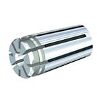
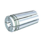
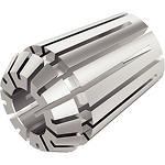
Produto semelhante ao:
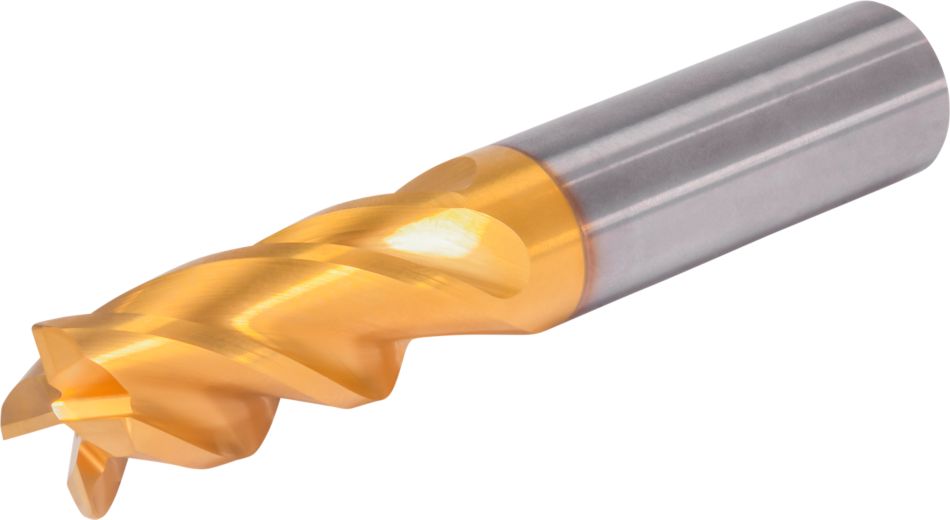
GOmill™ PRO • Ball Nose • 4 Flutes • Necked • Weldon Shank • Metric
Solid Carbide End Mill for Roughing and Finishing of Multiple Materials
Número de material7231265
ID do catálogo ISOGOPR4BN0500R013HBMID do catálogo ANSIGOPR4BN0500R013HBM
- P Steel
- M Stainless Steel
- K Cast Iron
- N Non-Ferrous
- S High-Temp Alloys
- H Hardened Materials
Fresamento helicoidal
Fresamento de rampa: blank
Abertura de canal: ponta esférica
Fresamento lateral/fresamento de canto: ponta esférica
Fresamento de perfil 3D
Corner Style: Ball Nose
Haste — Cilíndrica Weldon
Sending to {{cadTool}} in progress...
Downloaded file will be available after import in the {{cadTool}} tool library.
| Número de material | 7231265 |
| ID do catálogo ISO | GOPR4BN0500R013HBM |
| ID do catálogo ANSI | GOPR4BN0500R013HBM |
| Grade | KCU20 |
| Adapter Style Machine Side | Weldon |
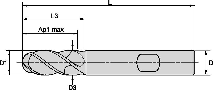
| [D1] Effective Cutting Diameter | 5 mm |
| [D1] Effective Cutting Diameter | 0.1969 in |
| [D] Adapter / Shank / Bore Diameter | 6 mm |
| [D] Adapter / Shank / Bore Diameter | 0.2362 in |
| [D3] Neck Diameter | 4.7 mm |
| [D3] Neck Diameter | 0.185 in |
| [AP1MAX] 1st Maximum Cutting Depth | 13 mm |
| [AP1MAX] 1st Maximum Cutting Depth | 0.5118 in |
| [L3] Usable Length | 18 mm |
| [L3] Usable Length | 0.7087 in |
| [L] Overall Length | 57 mm |
| [L] Overall Length | 2.2441 in |
| [R] Profile or Ball Nose Radii | 2.5 mm |
| [R] Raio de ponta esférica ou de perfil | 0.098 in |
| [Z] Number of Flutes | 4 |
Materiais das peças
- Steel
- Stainless Steel
- Cast Iron
- Non-Ferrous
- High-Temp Alloys
- Hardened Materials
Usos e aplicações
Fresamento helicoidal
Fresamento de rampa: blank
Abertura de canal: ponta esférica
Fresamento lateral/fresamento de canto: ponta esférica
Fresamento de perfil 3D
Corner Style: Ball Nose
Haste — Cilíndrica Weldon
Características e benefícios
- Unequal flute spacing for better vibration control and tool life.
- Multilayer TiN/TiALN coating for high performance at medium-high cutting on steels, stainless steels and cast iron.
- Ideal for shops working in the general engineering, transportation, energy and medical industries.
- Designed for side and shoulder milling, helical milling, pocketing, slotting and ramping.
Criar solução para calcular avanços e velocidade
Após criar uma solução basta escolher o ícone Avanços & Velocidades e o nosso sistema irá fornecer recomendações. Pode personalizar as informações adicionando a sua máquina e especificações ou fazer ajustes utilizando os controlos deslizantes.
Dados de aplicação
| Adjustment factors for speed (Vc) and feed (Fz) • Metric | |||||||||||
| Ae/D1 | 2% | 4% | 5% | 8% | 10% | 12% | 20% | 30% | 40% | 50% | 100% |
| Kv | 2.1 - 3.6 | 1.6 - 3 | 1.6 - 2.5 | 1.6 | 1.4 | 1.38 | 1.3 | 1.2 | 1.1 | 1 | 1 |
| KFz | 3.58 | 2.56 | 2.3 | 1.84 | 1.67 | 1.54 | 1.25 | 1.09 | 1.02 | 1 | 0.9 |
| Note: Identify the radial engagement per percentage of the tool diameter (Ae/D1). That column will give you the factor to multiply the Base SMF and Base IPT on the Speed and Feed original table Kv = Factor to multiply the Speed by KFz = Factor to multiply the Feed by | |||||||||||
| To calculate application specific cutting data, please use Kv coefficient, and KFz from tables for adaption of cutting speeds and feeds respectively: Vc new = Vc * Kv IPT new = IPT * KFz | Sample Calculation Material: P5 D1: 14.0 mm Ae: 20% of D1 Recommended Speed Vc : 80 m/min Recommended Feed Fz: 0.063 mm/th Adjustment coefficient Kv : 1.30 Adjustment coefficient KFz : 1.25 | Final cutting data recommendation: Vc new = 80 * 1.30 = 104 m/min Fz new = 0.063 * 1.30 = 0.079 mm/th | |||||||||
| GOmill™ PRO • Regular • Recommended Starting Speed and Feed [Metric] | ||||||||||||||||||||
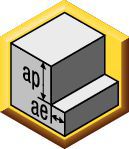 | 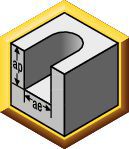 |  | ||||||||||||||||||
| KCU25 | Avanço por faca recomendado (fz = mm/faca) para fresamento lateral (A). Para abertura de canal (B), reduzir fz em 20%. | |||||||||||||||||||
| Fresamento lateral | Abertura de canal | Velocidade de corte | D1 | |||||||||||||||||
| Grupo de material | ap | ae | ap | Mín. | Início | Máx. | mm | 2,0 | 3,0 | 4,0 | 5,0 | 6,0 | 8,0 | 10,0 | 12,0 | 14,0 | 16,0 | 18,0 | 20,0 | 25,0 |
| P0 | Ap1 Max | 0,4 x D1 | 1,0 x D1 | 150 | 175 | 200 | fz | 0.014 | 0.021 | 0.028 | 0.036 | 0.044 | 0.060 | 0.072 | 0.083 | 0.092 | 0.101 | 0.108 | 0.114 | 0.124 |
| P1 | Ap1 Max | 0,4 x D1 | 1,0 x D1 | 150 | 175 | 200 | fz | 0.014 | 0.021 | 0.028 | 0.036 | 0.044 | 0.060 | 0.072 | 0.083 | 0.092 | 0.101 | 0.108 | 0.114 | 0.124 |
| P2 | Ap1 Max | 0,4 x D1 | 1,0 x D1 | 140 | 165 | 190 | fz | 0.014 | 0.021 | 0.028 | 0.036 | 0.044 | 0.060 | 0.072 | 0.083 | 0.092 | 0.101 | 0.108 | 0.114 | 0.124 |
| P3 | Ap1 Max | 0,4 x D1 | 1,0 x D1 | 120 | 140 | 160 | fz | 0.011 | 0.017 | 0.023 | 0.030 | 0.036 | 0.050 | 0.061 | 0.070 | 0.079 | 0.087 | 0.095 | 0.101 | 0.114 |
| P4 | Ap1 Max | 0,4 x D1 | 0,75 x D1 | 90 | 120 | 150 | fz | 0.010 | 0.016 | 0.021 | 0.027 | 0.033 | 0.045 | 0.054 | 0.062 | 0.070 | 0.077 | 0.083 | 0.088 | 0.098 |
| P5 | Ap1 Max | 0,4 x D1 | 1,0 x D1 | 60 | 80 | 100 | fz | 0.009 | 0.014 | 0.019 | 0.024 | 0.029 | 0.040 | 0.048 | 0.056 | 0.063 | 0.070 | 0.076 | 0.081 | 0.091 |
| P6 | Ap1 Max | 0,4 x D1 | 0,75 x D1 | 50 | 63 | 75 | fz | 0.008 | 0.012 | 0.016 | 0.020 | 0.025 | 0.034 | 0.040 | 0.047 | 0.052 | 0.057 | 0.061 | 0.065 | 0.071 |
| M1 | Ap1 Max | 0,4 x D1 | 1,0 x D1 | 90 | 103 | 115 | fz | 0.011 | 0.017 | 0.023 | 0.030 | 0.036 | 0.050 | 0.061 | 0.070 | 0.079 | 0.087 | 0.095 | 0.101 | 0.114 |
| M2 | Ap1 Max | 0,4 x D1 | 1,0 x D1 | 60 | 70 | 80 | fz | 0.009 | 0.014 | 0.019 | 0.024 | 0.029 | 0.040 | 0.048 | 0.056 | 0.063 | 0.070 | 0.076 | 0.081 | 0.091 |
| M3 | Ap1 Max | 0,4 x D1 | 1,0 x D1 | 60 | 65 | 70 | fz | 0.008 | 0.012 | 0.016 | 0.020 | 0.025 | 0.034 | 0.040 | 0.047 | 0.052 | 0.057 | 0.061 | 0.065 | 0.071 |
| K1 | Ap1 Max | 0,4 x D1 | 1,0 x D1 | 120 | 135 | 150 | fz | 0.014 | 0.021 | 0.028 | 0.036 | 0.044 | 0.060 | 0.072 | 0.083 | 0.092 | 0.101 | 0.108 | 0.114 | 0.124 |
| K2 | Ap1 Max | 0,4 x D1 | 1,0 x D1 | 110 | 125 | 140 | fz | 0.011 | 0.017 | 0.023 | 0.030 | 0.036 | 0.050 | 0.061 | 0.070 | 0.079 | 0.087 | 0.095 | 0.101 | 0.114 |
| K3 | Ap1 Max | 0,4 x D1 | 1,0 x D1 | 110 | 120 | 130 | fz | 0.009 | 0.014 | 0.019 | 0.024 | 0.029 | 0.040 | 0.048 | 0.056 | 0.063 | 0.070 | 0.076 | 0.081 | 0.091 |
| S1 | Ap1 Max | 0,4 x D1 | 0,3 x D1 | 50 | 70 | 90 | fz | 0.011 | 0.017 | 0.023 | 0.030 | 0.036 | 0.050 | 0.061 | 0.070 | 0.079 | 0.087 | 0.095 | 0.101 | 0.114 |
| S2 | Ap1 Max | 0,4 x D1 | 0,3 x D1 | 25 | 38 | 50 | fz | 0.006 | 0.009 | 0.013 | 0.016 | 0.019 | 0.026 | 0.032 | 0.037 | 0.042 | 0.046 | 0.050 | 0.054 | 0.061 |
| S3 | Ap1 Max | 0,4 x D1 | 1,0 x D1 | 25 | 33 | 40 | fz | 0.006 | 0.009 | 0.013 | 0.016 | 0.019 | 0.026 | 0.032 | 0.037 | 0.042 | 0.046 | 0.050 | 0.054 | 0.061 |
| S4 | Ap1 Max | 0,4 x D1 | 1,0 x D1 | 50 | 55 | 60 | fz | 0.007 | 0.011 | 0.016 | 0.021 | 0.026 | 0.037 | 0.045 | 0.052 | 0.058 | 0.064 | 0.069 | 0.074 | 0.084 |
| H1 | Ap1 Max | 0,4 x D1 | 0,75 x D1 | 80 | 110 | 140 | fz | 0.010 | 0.016 | 0.021 | 0.027 | 0.033 | 0.045 | 0.054 | 0.062 | 0.070 | 0.077 | 0.083 | 0.088 | 0.098 |
| H2 | Ap1 Max | 0,4 x D1 | 0,5 x D1 | 70 | 95 | 120 | fz | 0.008 | 0.012 | 0.016 | 0.020 | 0.025 | 0.034 | 0.040 | 0.047 | 0.052 | 0.057 | 0.061 | 0.065 | 0.071 |
| Lower value of cuting speed is used for high stock removal applications or for higher hardness (machinability) within group. Higher value of cuting speed is used for finishing applications or for lower hardness (machinability) within group. Above parameters are based on ideal conditions. For smaller taper machining centers, please adjust parameters accordiongly on diameters greater than 12mm. For better surface finish reduce feed per tooth. Side and Slotting milling aplications: for longest reach (L3) tools, reduce Ae by 30%. Sharp corner tools not recommended for sloting aplication. | ||||||||||||||||||||
| Adjustment factors for speed (Vc) and feed (Fz) • Metric | |||||||||||
| Ae/D1 | 2% | 4% | 5% | 8% | 10% | 12% | 20% | 30% | 40% | 50% | 100% |
| Kv | 2.1 - 3.6 | 1.6 - 3 | 1.6 - 2.5 | 1.6 | 1.4 | 1.38 | 1.3 | 1.2 | 1.1 | 1 | 1 |
| KFz | 3.58 | 2.56 | 2.3 | 1.84 | 1.67 | 1.54 | 1.25 | 1.09 | 1.02 | 1 | 0.9 |
| Note: Identify the radial engagement per percentage of the tool diameter (Ae/D1). That column will give you the factor to multiply the Base SMF and Base IPT on the Speed and Feed original table Kv = Factor to multiply the Speed by KFz = Factor to multiply the Feed by | |||||||||||
| To calculate application specific cutting data, please use Kv coefficient, and KFz from tables for adaption of cutting speeds and feeds respectively: Vc new = Vc * Kv IPT new = IPT * KFz | Sample Calculation Material: P5 D1: 14.0 mm Ae: 20% of D1 Recommended Speed Vc : 80 m/min Recommended Feed Fz: 0.063 mm/th Adjustment coefficient Kv : 1.30 Adjustment coefficient KFz : 1.25 | Final cutting data recommendation: Vc new = 80 * 1.30 = 104 m/min Fz new = 0.063 * 1.30 = 0.079 mm/th | |||||||||
| GOmill™ PRO • Long • Recommended Starting Speed and Feed [Metric] | ||||||||||||||||||
 |  | |||||||||||||||||
| KCU25 | Avanço por faca recomendado (fz = mm/faca) para fresamento lateral (A). Para abertura de canal (B), reduzir fz em 20%. | |||||||||||||||||
| Fresamento lateral | Velocidade de corte | D1 | ||||||||||||||||
| Grupo de material | ap | ae | Mín. | Início | Máx. | mm | 2,0 | 3,0 | 4,0 | 5,0 | 6,0 | 8,0 | 10,0 | 12,0 | 14,0 | 18,0 | 20,0 | 25,0 |
| P0 | Ap1 Max | 0.2xD | 150 | 175 | 200 | fz | 0.014 | 0.021 | 0.028 | 0.036 | 0.044 | 0.060 | 0.072 | 0.083 | 0.092 | 0.108 | 0.114 | 0.124 |
| P1 | Ap1 Max | 0.2xD | 150 | 175 | 200 | fz | 0.014 | 0.021 | 0.028 | 0.036 | 0.044 | 0.060 | 0.072 | 0.083 | 0.092 | 0.108 | 0.114 | 0.124 |
| P2 | Ap1 Max | 0.2xD | 140 | 165 | 190 | fz | 0.014 | 0.021 | 0.028 | 0.036 | 0.044 | 0.060 | 0.072 | 0.083 | 0.092 | 0.108 | 0.114 | 0.124 |
| P3 | Ap1 Max | 0.2xD | 120 | 140 | 160 | fz | 0.011 | 0.017 | 0.023 | 0.030 | 0.036 | 0.050 | 0.061 | 0.070 | 0.079 | 0.095 | 0.101 | 0.114 |
| P4 | Ap1 Max | 0.2xD | 90 | 120 | 150 | fz | 0.010 | 0.016 | 0.021 | 0.027 | 0.033 | 0.045 | 0.054 | 0.062 | 0.070 | 0.083 | 0.088 | 0.098 |
| P5 | Ap1 Max | 0.2xD | 60 | 80 | 100 | fz | 0.009 | 0.014 | 0.019 | 0.024 | 0.029 | 0.040 | 0.048 | 0.056 | 0.063 | 0.076 | 0.081 | 0.091 |
| P6 | Ap1 Max | 0.15xD | 50 | 63 | 75 | fz | 0.008 | 0.012 | 0.016 | 0.020 | 0.025 | 0.034 | 0.040 | 0.047 | 0.052 | 0.061 | 0.065 | 0.071 |
| M1 | Ap1 Max | 0.2xD | 90 | 103 | 115 | fz | 0.011 | 0.017 | 0.023 | 0.030 | 0.036 | 0.050 | 0.061 | 0.070 | 0.079 | 0.095 | 0.101 | 0.114 |
| M2 | Ap1 Max | 0.2xD | 60 | 70 | 80 | fz | 0.009 | 0.014 | 0.019 | 0.024 | 0.029 | 0.040 | 0.048 | 0.056 | 0.063 | 0.076 | 0.081 | 0.091 |
| M3 | Ap1 Max | 0.2xD | 60 | 65 | 70 | fz | 0.008 | 0.012 | 0.016 | 0.020 | 0.025 | 0.034 | 0.040 | 0.047 | 0.052 | 0.061 | 0.065 | 0.071 |
| K1 | Ap1 Max | 0.2xD | 120 | 135 | 150 | fz | 0.014 | 0.021 | 0.028 | 0.036 | 0.044 | 0.060 | 0.072 | 0.083 | 0.092 | 0.108 | 0.114 | 0.124 |
| K2 | Ap1 Max | 0.2xD | 110 | 125 | 140 | fz | 0.011 | 0.017 | 0.023 | 0.030 | 0.036 | 0.050 | 0.061 | 0.070 | 0.079 | 0.095 | 0.101 | 0.114 |
| K3 | Ap1 Max | 0.2xD | 110 | 120 | 130 | fz | 0.009 | 0.014 | 0.019 | 0.024 | 0.029 | 0.040 | 0.048 | 0.056 | 0.063 | 0.076 | 0.081 | 0.091 |
| S1 | Ap1 Max | 0.1xD | 50 | 70 | 90 | fz | 0.011 | 0.017 | 0.023 | 0.030 | 0.036 | 0.050 | 0.061 | 0.070 | 0.079 | 0.095 | 0.101 | 0.114 |
| S2 | Ap1 Max | 0.1xD | 25 | 38 | 50 | fz | 0.006 | 0.009 | 0.013 | 0.016 | 0.019 | 0.026 | 0.032 | 0.037 | 0.042 | 0.050 | 0.054 | 0.061 |
| S3 | Ap1 Max | 0.1xD | 25 | 33 | 40 | fz | 0.006 | 0.009 | 0.013 | 0.016 | 0.019 | 0.026 | 0.032 | 0.037 | 0.042 | 0.050 | 0.054 | 0.061 |
| S4 | Ap1 Max | 0.15xD | 50 | 55 | 60 | fz | 0.007 | 0.011 | 0.016 | 0.021 | 0.026 | 0.037 | 0.045 | 0.052 | 0.058 | 0.069 | 0.074 | 0.084 |
| H1 | Ap1 Max | 0.15xD | 80 | 110 | 140 | fz | 0.010 | 0.016 | 0.021 | 0.027 | 0.033 | 0.045 | 0.054 | 0.062 | 0.070 | 0.083 | 0.088 | 0.098 |
| H2 | Ap1 Max | 0.15xD | 70 | 95 | 120 | fz | 0.008 | 0.012 | 0.016 | 0.020 | 0.025 | 0.034 | 0.040 | 0.047 | 0.052 | 0.061 | 0.065 | 0.071 |
| Lower value of cuting speed is used for high stock removal applications or for higher hardness (machinability) within group. Higher value of cuting speed is used for finishing applications or for lower hardness (machinability) within group. Above parameters are based on ideal conditions. For smaller taper machining centers, please adjust parameters accordiongly on diameters greater than 12mm. For better surface finish reduce feed per tooth. Side milling aplications: for longest reach (L3) tools, reduce Ae by 30%. Sharp corner tools not recommended for sloting aplication. | ||||||||||||||||||
TechnicalInfo
| Angle of engagement (phi°) relative to cutting width (Ae) |  | ||||||||||
| ae | 2% | 5% | 7.50% | 10% | 15% | 20% | 30% | 40% | 50% | 100% | |
| phi - angle of engagement | 16.26 | 25.84 | 31.79 | 36.87 | 45.57 | 53.13 | 66.42 | 78.46 | 90 | 180 | |
I have read and accepted the Terms & Conditions of use
CAD Drawings Models
Can’t find the file type you’re looking for?
Product data


