定価
/個
割引
価格
/個
販売包装単位 0最小包装サイズに合わせて調整されています。
最小数量: 0包装サイズ要件に合わせて調整されています。
在庫ありこの製品は既に廃盤になっております長納期品


 +0
+0
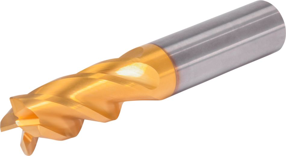
 ヘリカルミーリング
 ランピング加工:ブランク
 溝加工:ボールノーズ
 側面加工/ショルダー加工:ボールノーズ
 3Dプロファイル加工
 Corner Style: Ball Nose
 シャンク — ストレートWeldon
Downloaded file will be available after import in the {{cadTool}} tool library.
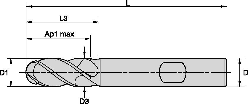
| 製品番号 | 7231265 |
| ISO カタログ ID | GOPR4BN0500R013HBM |
| ANSIカタログID | GOPR4BN0500R013HBM |
| Grade | KCU20 |
| Adapter Style Machine Side | Weldon |
| [D1] Effective Cutting Diameter | 5 mm |
| [D1] Effective Cutting Diameter | 0.1969 in |
| [D] Adapter / Shank / Bore Diameter | 6 mm |
| [D] Adapter / Shank / Bore Diameter | 0.2362 in |
| [D3] Neck Diameter | 4.7 mm |
| [D3] Neck Diameter | 0.185 in |
| [AP1MAX] 1st Maximum Cutting Depth | 13 mm |
| [AP1MAX] 1st Maximum Cutting Depth | 0.5118 in |
| [L3] Usable Length | 18 mm |
| [L3] Usable Length | 0.7087 in |
| [L] Overall Length | 57 mm |
| [L] Overall Length | 2.2441 in |
| [R] Profile or Ball Nose Radii | 2.5 mm |
| [R]プロファイルまたはボールノーズ半径 | 0.098 in |
| [Z] Number of Flutes | 4 |
ヘリカルミーリングランピング加工:ブランク溝加工:ボールノーズ側面加工/ショルダー加工:ボールノーズ3Dプロファイル加工Corner Style: Ball Noseシャンク — ストレートWeldon送りと速度を計算するソリューションを作成する
ソリューションを作成したら、送りと速度アイコンを選択するだけで、システムが推奨事項を提供します。マシンと仕様を追加して情報をカスタマイズしたり、スライダーを使用して調整することもできます。
| Adjustment factors for speed (Vc) and feed (Fz) • Metric | |||||||||||
| Ae/D1 | 2% | 4% | 5% | 8% | 10% | 12% | 20% | 30% | 40% | 50% | 100% |
| Kv | 2.1 - 3.6 | 1.6 - 3 | 1.6 - 2.5 | 1.6 | 1.4 | 1.38 | 1.3 | 1.2 | 1.1 | 1 | 1 |
| KFz | 3.58 | 2.56 | 2.3 | 1.84 | 1.67 | 1.54 | 1.25 | 1.09 | 1.02 | 1 | 0.9 |
| Note: Identify the radial engagement per percentage of the tool diameter (Ae/D1). That column will give you the factor to multiply the Base SMF and Base IPT on the Speed and Feed original table Kv = Factor to multiply the Speed by KFz = Factor to multiply the Feed by | |||||||||||
| To calculate application specific cutting data, please use Kv coefficient, and KFz from tables for adaption of cutting speeds and feeds respectively: Vc new = Vc * Kv IPT new = IPT * KFz | Sample Calculation Material: P5 D1: 14.0 mm Ae: 20% of D1 Recommended Speed Vc : 80 m/min Recommended Feed Fz: 0.063 mm/th Adjustment coefficient Kv : 1.30 Adjustment coefficient KFz : 1.25 | Final cutting data recommendation: Vc new = 80 * 1.30 = 104 m/min Fz new = 0.063 * 1.30 = 0.079 mm/th | |||||||||
| GOmill™ PRO • Regular • Recommended Starting Speed and Feed [Metric] | ||||||||||||||||||||
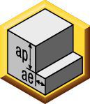 | 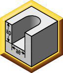 |  | ||||||||||||||||||
| KCU25 | 側面加工(A)の1刃あたりの推奨送り量(fz = mm/th)。 溝加工(B)の場合は、fzを20%下げた値。 | |||||||||||||||||||
| 側面加工 | 溝加工 | 切削速度 | エンドミル径 | |||||||||||||||||
| 被削材 グループ | ap | ae | ap | 最小 | スタート | 最大 | mm | 2,0 | 3,0 | 4,0 | 5,0 | 6,0 | 8,0 | 10,0 | 12,0 | 14,0 | 16,0 | 18,0 | 20,0 | 25,0 |
| P0 | Ap1 Max | 0,4 x D1 | 1,0 x D1 | 150 | 175 | 200 | fz | 0.014 | 0.021 | 0.028 | 0.036 | 0.044 | 0.060 | 0.072 | 0.083 | 0.092 | 0.101 | 0.108 | 0.114 | 0.124 |
| P1 | Ap1 Max | 0,4 x D1 | 1,0 x D1 | 150 | 175 | 200 | fz | 0.014 | 0.021 | 0.028 | 0.036 | 0.044 | 0.060 | 0.072 | 0.083 | 0.092 | 0.101 | 0.108 | 0.114 | 0.124 |
| P2 | Ap1 Max | 0,4 x D1 | 1,0 x D1 | 140 | 165 | 190 | fz | 0.014 | 0.021 | 0.028 | 0.036 | 0.044 | 0.060 | 0.072 | 0.083 | 0.092 | 0.101 | 0.108 | 0.114 | 0.124 |
| P3 | Ap1 Max | 0,4 x D1 | 1,0 x D1 | 120 | 140 | 160 | fz | 0.011 | 0.017 | 0.023 | 0.030 | 0.036 | 0.050 | 0.061 | 0.070 | 0.079 | 0.087 | 0.095 | 0.101 | 0.114 |
| P4 | Ap1 Max | 0,4 x D1 | 0,75 x D1 | 90 | 120 | 150 | fz | 0.010 | 0.016 | 0.021 | 0.027 | 0.033 | 0.045 | 0.054 | 0.062 | 0.070 | 0.077 | 0.083 | 0.088 | 0.098 |
| P5 | Ap1 Max | 0,4 x D1 | 1,0 x D1 | 60 | 80 | 100 | fz | 0.009 | 0.014 | 0.019 | 0.024 | 0.029 | 0.040 | 0.048 | 0.056 | 0.063 | 0.070 | 0.076 | 0.081 | 0.091 |
| P6 | Ap1 Max | 0,4 x D1 | 0,75 x D1 | 50 | 63 | 75 | fz | 0.008 | 0.012 | 0.016 | 0.020 | 0.025 | 0.034 | 0.040 | 0.047 | 0.052 | 0.057 | 0.061 | 0.065 | 0.071 |
| M1 | Ap1 Max | 0,4 x D1 | 1,0 x D1 | 90 | 103 | 115 | fz | 0.011 | 0.017 | 0.023 | 0.030 | 0.036 | 0.050 | 0.061 | 0.070 | 0.079 | 0.087 | 0.095 | 0.101 | 0.114 |
| M2 | Ap1 Max | 0,4 x D1 | 1,0 x D1 | 60 | 70 | 80 | fz | 0.009 | 0.014 | 0.019 | 0.024 | 0.029 | 0.040 | 0.048 | 0.056 | 0.063 | 0.070 | 0.076 | 0.081 | 0.091 |
| M3 | Ap1 Max | 0,4 x D1 | 1,0 x D1 | 60 | 65 | 70 | fz | 0.008 | 0.012 | 0.016 | 0.020 | 0.025 | 0.034 | 0.040 | 0.047 | 0.052 | 0.057 | 0.061 | 0.065 | 0.071 |
| K1 | Ap1 Max | 0,4 x D1 | 1,0 x D1 | 120 | 135 | 150 | fz | 0.014 | 0.021 | 0.028 | 0.036 | 0.044 | 0.060 | 0.072 | 0.083 | 0.092 | 0.101 | 0.108 | 0.114 | 0.124 |
| K2 | Ap1 Max | 0,4 x D1 | 1,0 x D1 | 110 | 125 | 140 | fz | 0.011 | 0.017 | 0.023 | 0.030 | 0.036 | 0.050 | 0.061 | 0.070 | 0.079 | 0.087 | 0.095 | 0.101 | 0.114 |
| K3 | Ap1 Max | 0,4 x D1 | 1,0 x D1 | 110 | 120 | 130 | fz | 0.009 | 0.014 | 0.019 | 0.024 | 0.029 | 0.040 | 0.048 | 0.056 | 0.063 | 0.070 | 0.076 | 0.081 | 0.091 |
| S1 | Ap1 Max | 0,4 x D1 | 0,3 x D1 | 50 | 70 | 90 | fz | 0.011 | 0.017 | 0.023 | 0.030 | 0.036 | 0.050 | 0.061 | 0.070 | 0.079 | 0.087 | 0.095 | 0.101 | 0.114 |
| S2 | Ap1 Max | 0,4 x D1 | 0,3 x D1 | 25 | 38 | 50 | fz | 0.006 | 0.009 | 0.013 | 0.016 | 0.019 | 0.026 | 0.032 | 0.037 | 0.042 | 0.046 | 0.050 | 0.054 | 0.061 |
| S3 | Ap1 Max | 0,4 x D1 | 1,0 x D1 | 25 | 33 | 40 | fz | 0.006 | 0.009 | 0.013 | 0.016 | 0.019 | 0.026 | 0.032 | 0.037 | 0.042 | 0.046 | 0.050 | 0.054 | 0.061 |
| S4 | Ap1 Max | 0,4 x D1 | 1,0 x D1 | 50 | 55 | 60 | fz | 0.007 | 0.011 | 0.016 | 0.021 | 0.026 | 0.037 | 0.045 | 0.052 | 0.058 | 0.064 | 0.069 | 0.074 | 0.084 |
| H1 | Ap1 Max | 0,4 x D1 | 0,75 x D1 | 80 | 110 | 140 | fz | 0.010 | 0.016 | 0.021 | 0.027 | 0.033 | 0.045 | 0.054 | 0.062 | 0.070 | 0.077 | 0.083 | 0.088 | 0.098 |
| H2 | Ap1 Max | 0,4 x D1 | 0,5 x D1 | 70 | 95 | 120 | fz | 0.008 | 0.012 | 0.016 | 0.020 | 0.025 | 0.034 | 0.040 | 0.047 | 0.052 | 0.057 | 0.061 | 0.065 | 0.071 |
| Lower value of cuting speed is used for high stock removal applications or for higher hardness (machinability) within group. Higher value of cuting speed is used for finishing applications or for lower hardness (machinability) within group. Above parameters are based on ideal conditions. For smaller taper machining centers, please adjust parameters accordiongly on diameters greater than 12mm. For better surface finish reduce feed per tooth. Side and Slotting milling aplications: for longest reach (L3) tools, reduce Ae by 30%. Sharp corner tools not recommended for sloting aplication. | ||||||||||||||||||||
| Adjustment factors for speed (Vc) and feed (Fz) • Metric | |||||||||||
| Ae/D1 | 2% | 4% | 5% | 8% | 10% | 12% | 20% | 30% | 40% | 50% | 100% |
| Kv | 2.1 - 3.6 | 1.6 - 3 | 1.6 - 2.5 | 1.6 | 1.4 | 1.38 | 1.3 | 1.2 | 1.1 | 1 | 1 |
| KFz | 3.58 | 2.56 | 2.3 | 1.84 | 1.67 | 1.54 | 1.25 | 1.09 | 1.02 | 1 | 0.9 |
| Note: Identify the radial engagement per percentage of the tool diameter (Ae/D1). That column will give you the factor to multiply the Base SMF and Base IPT on the Speed and Feed original table Kv = Factor to multiply the Speed by KFz = Factor to multiply the Feed by | |||||||||||
| To calculate application specific cutting data, please use Kv coefficient, and KFz from tables for adaption of cutting speeds and feeds respectively: Vc new = Vc * Kv IPT new = IPT * KFz | Sample Calculation Material: P5 D1: 14.0 mm Ae: 20% of D1 Recommended Speed Vc : 80 m/min Recommended Feed Fz: 0.063 mm/th Adjustment coefficient Kv : 1.30 Adjustment coefficient KFz : 1.25 | Final cutting data recommendation: Vc new = 80 * 1.30 = 104 m/min Fz new = 0.063 * 1.30 = 0.079 mm/th | |||||||||
| GOmill™ PRO • Long • Recommended Starting Speed and Feed [Metric] | ||||||||||||||||||
| | |||||||||||||||||
| KCU25 | 側面加工(A)の1刃あたりの推奨送り量(fz = mm/th)。 溝加工(B)の場合は、fzを20%下げた値。 | |||||||||||||||||
| 側面加工 | 切削速度 | エンドミル径 | ||||||||||||||||
| 被削材 グループ | ap | ae | 最小 | スタート | 最大 | mm | 2,0 | 3,0 | 4,0 | 5,0 | 6,0 | 8,0 | 10,0 | 12,0 | 14,0 | 18,0 | 20,0 | 25,0 |
| P0 | Ap1 Max | 0.2xD | 150 | 175 | 200 | fz | 0.014 | 0.021 | 0.028 | 0.036 | 0.044 | 0.060 | 0.072 | 0.083 | 0.092 | 0.108 | 0.114 | 0.124 |
| P1 | Ap1 Max | 0.2xD | 150 | 175 | 200 | fz | 0.014 | 0.021 | 0.028 | 0.036 | 0.044 | 0.060 | 0.072 | 0.083 | 0.092 | 0.108 | 0.114 | 0.124 |
| P2 | Ap1 Max | 0.2xD | 140 | 165 | 190 | fz | 0.014 | 0.021 | 0.028 | 0.036 | 0.044 | 0.060 | 0.072 | 0.083 | 0.092 | 0.108 | 0.114 | 0.124 |
| P3 | Ap1 Max | 0.2xD | 120 | 140 | 160 | fz | 0.011 | 0.017 | 0.023 | 0.030 | 0.036 | 0.050 | 0.061 | 0.070 | 0.079 | 0.095 | 0.101 | 0.114 |
| P4 | Ap1 Max | 0.2xD | 90 | 120 | 150 | fz | 0.010 | 0.016 | 0.021 | 0.027 | 0.033 | 0.045 | 0.054 | 0.062 | 0.070 | 0.083 | 0.088 | 0.098 |
| P5 | Ap1 Max | 0.2xD | 60 | 80 | 100 | fz | 0.009 | 0.014 | 0.019 | 0.024 | 0.029 | 0.040 | 0.048 | 0.056 | 0.063 | 0.076 | 0.081 | 0.091 |
| P6 | Ap1 Max | 0.15xD | 50 | 63 | 75 | fz | 0.008 | 0.012 | 0.016 | 0.020 | 0.025 | 0.034 | 0.040 | 0.047 | 0.052 | 0.061 | 0.065 | 0.071 |
| M1 | Ap1 Max | 0.2xD | 90 | 103 | 115 | fz | 0.011 | 0.017 | 0.023 | 0.030 | 0.036 | 0.050 | 0.061 | 0.070 | 0.079 | 0.095 | 0.101 | 0.114 |
| M2 | Ap1 Max | 0.2xD | 60 | 70 | 80 | fz | 0.009 | 0.014 | 0.019 | 0.024 | 0.029 | 0.040 | 0.048 | 0.056 | 0.063 | 0.076 | 0.081 | 0.091 |
| M3 | Ap1 Max | 0.2xD | 60 | 65 | 70 | fz | 0.008 | 0.012 | 0.016 | 0.020 | 0.025 | 0.034 | 0.040 | 0.047 | 0.052 | 0.061 | 0.065 | 0.071 |
| K1 | Ap1 Max | 0.2xD | 120 | 135 | 150 | fz | 0.014 | 0.021 | 0.028 | 0.036 | 0.044 | 0.060 | 0.072 | 0.083 | 0.092 | 0.108 | 0.114 | 0.124 |
| K2 | Ap1 Max | 0.2xD | 110 | 125 | 140 | fz | 0.011 | 0.017 | 0.023 | 0.030 | 0.036 | 0.050 | 0.061 | 0.070 | 0.079 | 0.095 | 0.101 | 0.114 |
| K3 | Ap1 Max | 0.2xD | 110 | 120 | 130 | fz | 0.009 | 0.014 | 0.019 | 0.024 | 0.029 | 0.040 | 0.048 | 0.056 | 0.063 | 0.076 | 0.081 | 0.091 |
| S1 | Ap1 Max | 0.1xD | 50 | 70 | 90 | fz | 0.011 | 0.017 | 0.023 | 0.030 | 0.036 | 0.050 | 0.061 | 0.070 | 0.079 | 0.095 | 0.101 | 0.114 |
| S2 | Ap1 Max | 0.1xD | 25 | 38 | 50 | fz | 0.006 | 0.009 | 0.013 | 0.016 | 0.019 | 0.026 | 0.032 | 0.037 | 0.042 | 0.050 | 0.054 | 0.061 |
| S3 | Ap1 Max | 0.1xD | 25 | 33 | 40 | fz | 0.006 | 0.009 | 0.013 | 0.016 | 0.019 | 0.026 | 0.032 | 0.037 | 0.042 | 0.050 | 0.054 | 0.061 |
| S4 | Ap1 Max | 0.15xD | 50 | 55 | 60 | fz | 0.007 | 0.011 | 0.016 | 0.021 | 0.026 | 0.037 | 0.045 | 0.052 | 0.058 | 0.069 | 0.074 | 0.084 |
| H1 | Ap1 Max | 0.15xD | 80 | 110 | 140 | fz | 0.010 | 0.016 | 0.021 | 0.027 | 0.033 | 0.045 | 0.054 | 0.062 | 0.070 | 0.083 | 0.088 | 0.098 |
| H2 | Ap1 Max | 0.15xD | 70 | 95 | 120 | fz | 0.008 | 0.012 | 0.016 | 0.020 | 0.025 | 0.034 | 0.040 | 0.047 | 0.052 | 0.061 | 0.065 | 0.071 |
| Lower value of cuting speed is used for high stock removal applications or for higher hardness (machinability) within group. Higher value of cuting speed is used for finishing applications or for lower hardness (machinability) within group. Above parameters are based on ideal conditions. For smaller taper machining centers, please adjust parameters accordiongly on diameters greater than 12mm. For better surface finish reduce feed per tooth. Side milling aplications: for longest reach (L3) tools, reduce Ae by 30%. Sharp corner tools not recommended for sloting aplication. | ||||||||||||||||||
| Angle of engagement (phi°) relative to cutting width (Ae) |  | ||||||||||
| ae | 2% | 5% | 7.50% | 10% | 15% | 20% | 30% | 40% | 50% | 100% | |
| phi - angle of engagement | 16.26 | 25.84 | 31.79 | 36.87 | 45.57 | 53.13 | 66.42 | 78.46 | 90 | 180 | |
I have read and accepted the Terms & Conditions of use


ISO製品型番
ANSI製品型番
to find similar products.Please select a file to download
Models
. Please enter the desired qty for the material(s) you want to include in your promotion or Proceed Without Promotion and only your base materials will be added to the cart.
Minimum quantity should be
| SAP Material Number | ISO製品型番 | 材種 |
|---|
You are about to leave the Solution building process.
Are you sure you want to leave?