Witamy
Potwierdź swoje preferencje
Aktualizuj preferencje
Sugestie dotyczące produktów
Product Family suggestions
Witaj, User Name
Wybrane konto:
Wystąpił problem z Twoim kontem. Skontaktuj się z działem obsługi klienta.
Konto kupującego
Zmień konto
Konto odbiorcy
Zmień konto
- Panel przyborów
- Zarządzaj zamówieniami
- Zarządzaj kanałami
- Książka adresowa
-
Powiadomienia
Oznacz wszystkie jako przeczytane - Zmień hasło
- Mój profil
- Wyloguj się
Pozycje
pomyślnie dodano do koszyka
Wyświetl koszyk
Wyświetl koszyk
Frezuj więcej za mniej dzięki naszym ofertom ograniczonym czasowo!
Kup teraz.
Pozycje
pomyślnie dodano do koszyka
Wyświetl koszyk
Wyświetl koszyk
Edytuj
Dodaj
Nazwa : {{SolutionName}}- Produkty
- /
- 0° LN Slotting Cutters • KS Narrow Slotting Cutters • Arbor Mount • Inch
Sending to SolidCAM in progress...
Downloaded file will be available after import in the SolidCAM tool library.
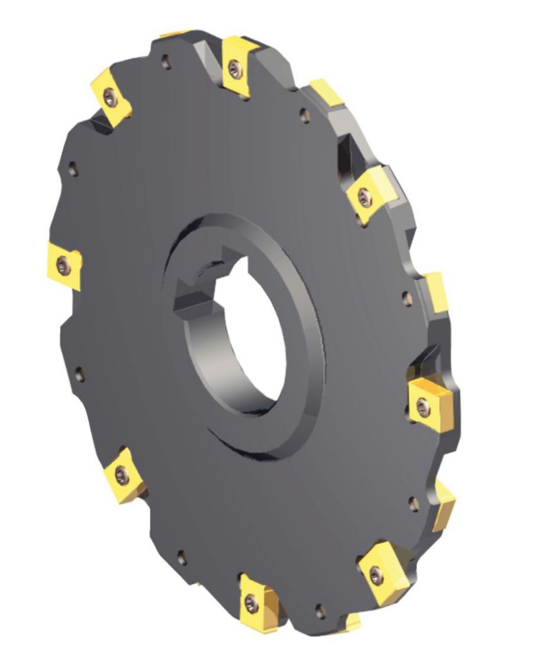
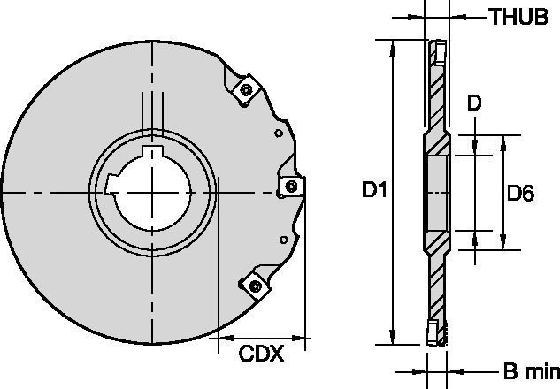
0° LN Slotting Cutters • KS Narrow Slotting Cutters • Arbor Mount • Inch
KS Narrow Slotting Cutters • Arbor Mount
Właściwości i zalety
- .250" to .500" slot width range.
- Easy width adjustment through insert thickness.
- Full side and face cutting.
- Neutral and positive chip forming inserts are standard.
- Four insert cutting edges.
- Two keyways for staggered mounting.
- Requires only one spare part.
Zastosowania
Slotting: Side
| LN Slotting Series • Insert Selection Guide | ||||||
| Material Group | Light
|
General
|
Heavy
|
|||
| – | (Light geometry) | – | (Strong geometry) | |||
| – | wear
|
 <="" td=""> <="" td=""> | toughness | |||
| – | Geometry | Grade | Geometry | Grade | Geometry | Grade |
| P1-P2 | LNEU… | KCPM40 | LNEU…SGP | KCPM40 | LNEQ... | KC725M |
| P3-P4 | LNEU… | KCPK30 | LNEU…SGP | KCPM40 | LNEQ... | KC725M |
| P5-P6 | LNEU… | KC725M | LNEU…SGP | KC725M | LNEQ... | KC725M |
| M1-M2 | LNEU… | KC725M | LNEU…SGP | KC725M | LNEQ... | KC725M |
| M3 | LNEU… | KCPM40 | LNEU…SGP | KCPM40 | LNEQ... | KC725M |
| K1-K2 | LNEU… | KCK20B | LNEU… | KCK20B | LNEQ... | KCK15 |
| K3 | LNEU… | KCK20B | LNEQ... | KCK20B | LNEQ... | KCK20B |
| N1-N2 | – | – | – | – | – | – |
| N3 | – | – | – | – | – | – |
| S1-S2 | LNEU… | KC725M | LNEU…SGP | KC725M | LNEQ... | KC725M |
| S3 | LNEU… | KCPK30 | LNEU…SGP | KCPM40 | LNEQ... | KC725M |
| S4 | LNEU… | KC725M | LNEU…SGP | KC725M | LNEQ... | KC725M |
| H1 | – | – | – | – | – | – |
| LN Slotting Series • Recommended Starting Feeds [mm/th] | |||||||||||||||
| Insert Geometry | Recommended Starting Feed per Tooth (Fz) in Relation to % of Radial Engagement (ae) | ||||||||||||||
| 5% | 10% | 20% | 30% | 40–100% | |||||||||||
| L | M | H | L | M | H | L | M | H | L | M | H | L | M | H | |
| LNEU… | 0.17 | 0.47 | 0.7 | 0.12 | 0.34 | 0.5 | 0.09 | 0.26 | 0.38 | 0.08 | 0.22 | 0.33 | 0.07 | 0.2 | 0.3 |
| LNEU…SGP | 0.23 | 0.52 | 0.81 | 0.17 | 0.37 | 0.58 | 0.13 | 0.28 | 0.43 | 0.11 | 0.24 | 0.38 | 0.1 | 0.22 | 0.35 |
| LNEQ... | 0.23 | 0.59 | 0.95 | 0.17 | 0.43 | 0.68 | 0.13 | 0.32 | 0.51 | 0.11 | 0.28 | 0.44 | 0.1 | 0.25 | 0.41 |
| L = Light Machining; M = Medium Machining; H = Heavy Machining NOTE: Use "Light Machining" values as starting feed rate. | |||||||||||||||
| Light
|
General
|
Heavy
|
| LN Slotting Series • Recommended Starting Speed [m/min] | |||||||||||||||||||
| Grade | KC520M | KC725M | KCK15 | KCPK30 | KCK20B | KCPM40 | |||||||||||||
| Chip Thickness hex mm | Min | Max | Min | Max | Min | Max | Min | Max | Min | Max | Min | Max | |||||||
| Material Group | Max | Start | Min | Max | Start | Min | Max | Start | Min | Max | Start | Min | Max | Start | Min | Max | Start | Min | |
| P | 1 | – | – | – | 260 | 230 | 215 | – | – | – | 455 | 395 | 370 | – | – | – | 295 | 260 | 245 |
| 2 | – | – | – | 220 | 190 | 160 | – | – | – | 280 | 255 | 230 | – | – | – | 250 | 215 | 180 | |
| 3 | – | – | – | 200 | 170 | 140 | – | – | – | 255 | 230 | 205 | – | – | – | 230 | 195 | 160 | |
| 4 | – | – | – | 180 | 150 | 120 | – | – | – | 225 | 185 | 160 | – | – | – | 205 | 170 | 135 | |
| 5 | – | – | – | 150 | 135 | 120 | – | – | – | 190 | 170 | 150 | – | – | – | 170 | 155 | 135 | |
| 6 | – | – | – | 130 | 100 | 80 | – | – | – | 160 | 135 | 110 | – | – | – | 150 | 115 | 90 | |
| M | 1 | – | – | – | 170 | 150 | 135 | – | – | – | 205 | 185 | 155 | – | – | – | 195 | 170 | 155 |
| 2 | – | – | – | 155 | 130 | 110 | – | – | – | 185 | 160 | 140 | – | – | – | 175 | 150 | 125 | |
| 3 | – | – | – | 115 | 100 | 80 | – | – | – | 145 | 130 | 115 | – | – | – | 130 | 115 | 90 | |
| K | 1 | 270 | 245 | 215 | – | – | – | 420 | 385 | 340 | 295 | 265 | 240 | 360 | 290 | 245 | – | – | – |
| 2 | 210 | 190 | 175 | – | – | – | 335 | 295 | 275 | 235 | 210 | 190 | 280 | 230 | 195 | – | – | – | |
| 3 | 175 | 160 | 145 | – | – | – | 280 | 250 | 230 | 195 | 175 | 160 | 210 | 175 | 140 | – | – | – | |
| N | 1 | – | – | – | – | – | – | – | – | – | – | – | – | – | – | – | – | – | – |
| 2 | – | – | – | – | – | – | – | – | – | – | – | – | – | – | – | – | – | – | |
| 3 | – | – | – | – | – | – | – | – | – | – | – | – | – | – | – | – | – | – | |
| S | 1 | – | – | – | 35 | 30 | 25 | – | – | – | – | – | – | – | – | – | 40 | 35 | 30 |
| 2 | – | – | – | 35 | 30 | 25 | – | – | – | – | – | – | – | – | – | 40 | 35 | 30 | |
| 3 | – | – | – | 45 | 35 | 25 | – | – | – | – | – | – | – | – | – | 50 | 40 | 30 | |
| 4 | – | – | – | 50 | 45 | 30 | – | – | – | 50 | 45 | 35 | – | – | – | 55 | 50 | 35 | |
| H | 1 | – | – | – | – | – | – | – | – | – | – | – | – | – | – | – | – | – | – |
| Recommended Starting Speed are pointing to 90° Shoulder Milling . Starting Speed for Face and Copy Milling can be Increased by 20 %. As the average chip thickness increases, speed should be decreased. Material groups P, M, K and H show recommended starting speeds for dry machining. For wet machining, reduce speed by 20%. Material groups N and S show recommended starting speeds for wet machining. Not recommended for dry machining. | |||||||||||||||||||