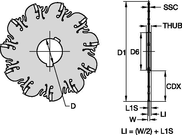
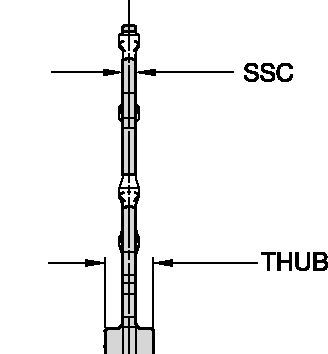
Frezy KNS® do frezowania rowków • Mocowanie w oprawce • Metryczne
Frezy KNS® do frezowania rowków • Mocowanie w oprawce
Właściwości i zalety
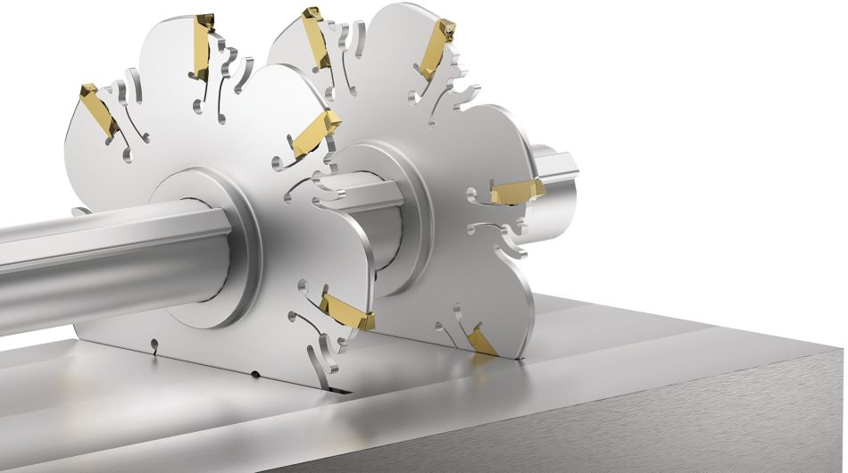
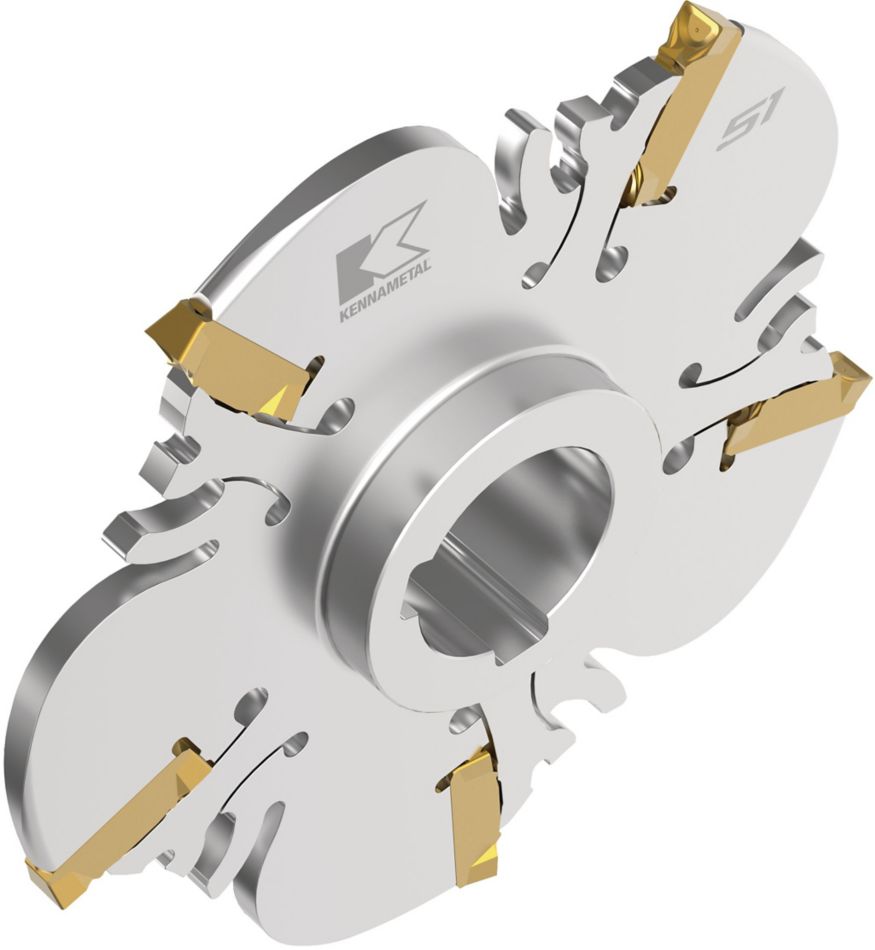
- Dwuwpustowa konstrukcja piasty do operacji wielokrotnego frezowania rowków.
- Pozytywowa geometria SGP łamacza wióra w zastosowaniach od obróbki lekkiej do ciężkiej zapewnia płynną pracę narzędzia i skuteczne odprowadzanie wiórów.
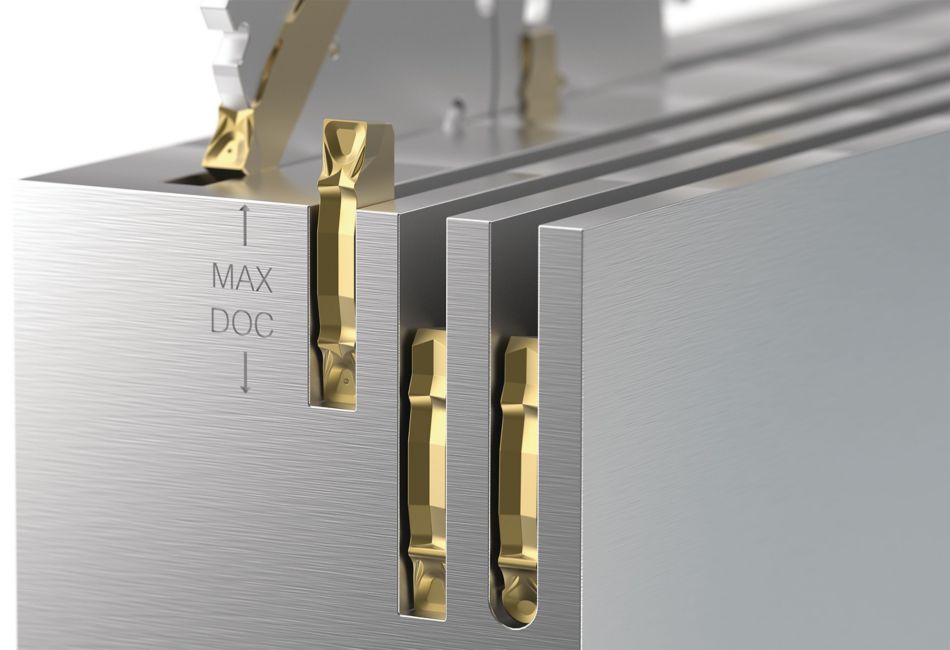
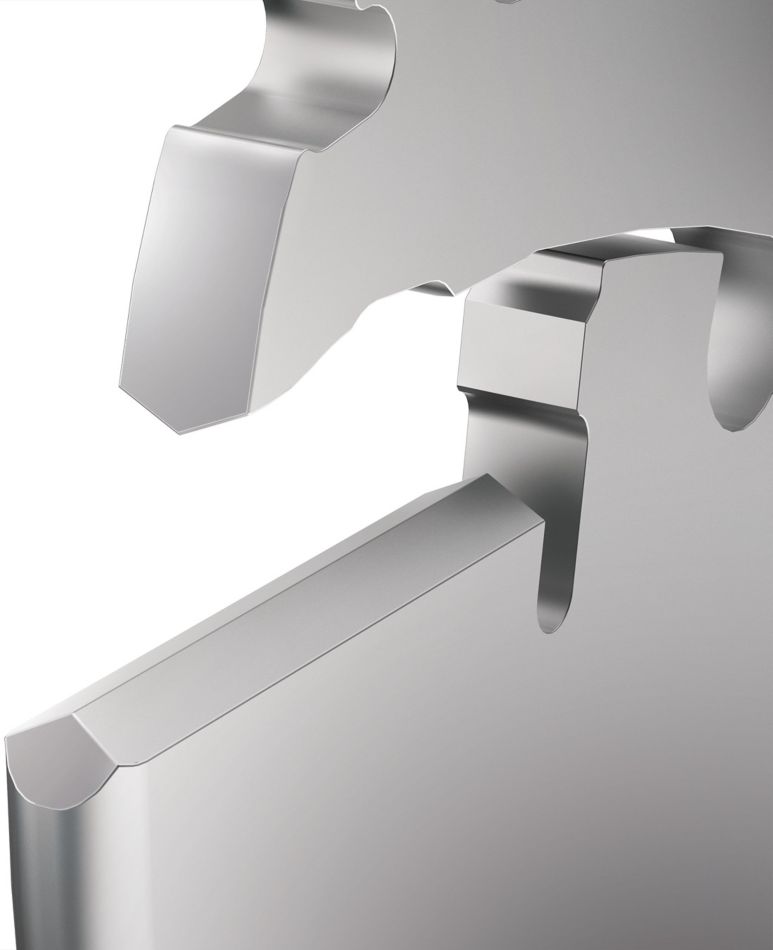
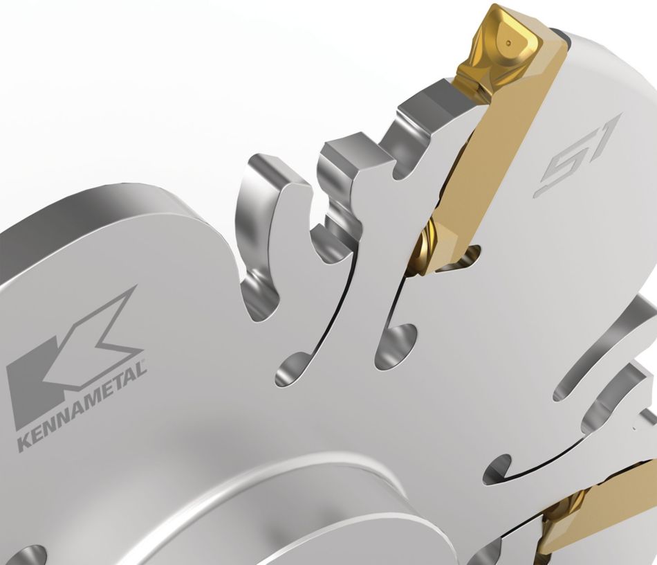
- Podwójny rowek typu V oraz gniazdo utrzymują płytkę na miejscu i minimalizują bicie promieniowe.
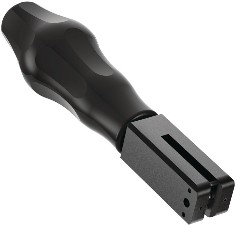
- Wyjątkowy mechanizm samozaciskowy zapewnia łatwą wymianę płytek.
Zastosowania
100055043
Slotting: Side
 <="" td="">