Witamy
Potwierdź swoje preferencje
Aktualizuj preferencje
Sugestie dotyczące produktów
Product Family suggestions
Witaj, User Name
Wybrane konto:
Wystąpił problem z Twoim kontem. Skontaktuj się z działem obsługi klienta.
Konto kupującego
Zmień konto
Konto odbiorcy
Zmień konto
- Panel przyborów
- Zarządzaj zamówieniami
- Zarządzaj kanałami
- Książka adresowa
-
Powiadomienia
Oznacz wszystkie jako przeczytane - Zmień hasło
- Mój profil
- Wyloguj się
Pozycje
pomyślnie dodano do koszyka
Wyświetl koszyk
Wyświetl koszyk
Frezuj więcej za mniej dzięki naszym ofertom ograniczonym czasowo!
Kup teraz.
Pozycje
pomyślnie dodano do koszyka
Wyświetl koszyk
Wyświetl koszyk
Edytuj
Dodaj
Nazwa : {{SolutionName}}- Produkty
- /
- Mill 1-7™ • End Mills • Cylindrical Shank • Inch
Sending to SolidCAM in progress...
Downloaded file will be available after import in the SolidCAM tool library.
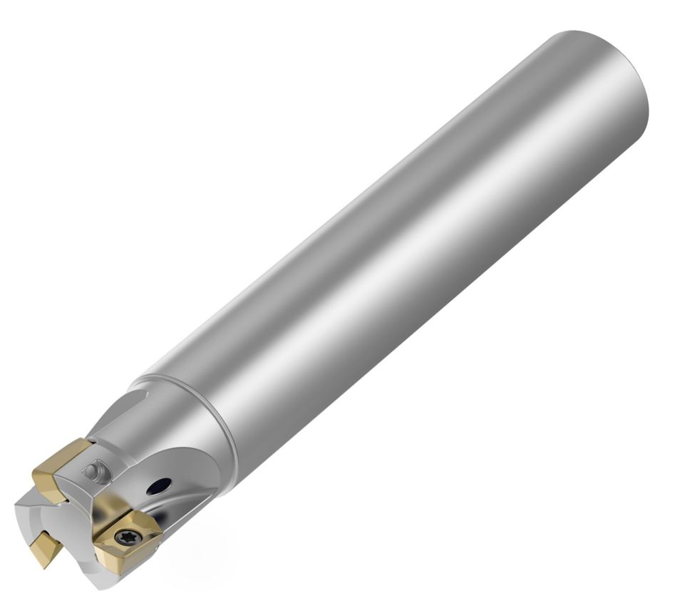
Mill 1-7™ • End Mills • Cylindrical Shank • Inch
Frezy składane trzpieniowe — Mill 1-7
Właściwości i zalety
- Mill 90° walls.
- Aggressive ramping rates.
- High speed machining.
- Ramp, slot, plunge, face, and shoulder milling.
Zastosowania
Face Milling
Helical Milling
Ramping: Blank
Slotting: Square End
Side Milling/Shoulder Milling: Square End
Shank - Cylindrical Plain
Milling - Through Coolant
Pocketing
Poradnik doboru płytek
| Material Group | Light
|
General
|
Heavy
|
|||
| – | (Light geometry) | – | (Strong geometry) | |||
| – | wear
|
 <="" td=""> <="" td=""> | toughness | |||
| – | Geometry | Grade | Geometry | Grade | Geometry | Grade |
| P1–P2 | .S..GE | KC725M | .S..GE | KCPK30 | .S..GE | KCPM40 |
| P3–P4 | .S..GE | KC725M | .S..GE | KCPK30 | .S..GE | KCPM40 |
| P5–P6 | .S..GE | KC725M | .S..GE | KCPK30 | .S..GE | KCPM40 |
| M1–M2 | .S..GE | KC522M | .S..GE | KC725M | .S..GE | KCPM40 |
| M3 | .S..GE | KC725M | .S..GE | KCPK30 | .S..GE | KCPM40 |
| K1–K2 | .S..GE | KCPK30 | .S..GE | KCPK30 | .S..GE | KCPK30 |
| K3 | .S..GE | KCPK30 | .S..GE | KCPK30 | .S..GE | KCPK30 |
| N1–N2 | – | – | – | – | – | – |
| N3 | – | – | – | – | – | – |
| S1–S2 | .S..GE | KC522M | .S..GE | KC725M | .S..GE | KC725M |
| S3 | .S..GE | KC725M | .S..GE | KC725M | .S..GE | KCPM40 |
| S4 | .S..GE | KC522M | .S..GE | KC725M | .S..GE | KC725M |
| H1 | – | – | – | – | – | – |
Zalecane wyjściowe wartości posuwu [mm]
| Mill 1-7™ • Recommended Starting Feeds [mm/th] | |||||||||||||||
| Insert Geometry | Recommended Starting Feed per Tooth (Fz) in Relation to % of Radial Engagement (ae) | ||||||||||||||
| 5% | 10% | 20% | 30% | 40–100% | |||||||||||
| L | M | H | L | M | H | L | M | H | L | M | H | L | M | H | |
| .S..GE | 0,23 | 0,47 | 0,69 | 0,17 | 0,34 | 0,50 | 0,13 | 0,26 | 0,37 | 0,11 | 0,22 | 0,32 | 0,10 | 0,20 | 0,30 |
| L = Light Machining; M = Medium Machining; H = Heavy Machining NOTE: Use Light Machining values as starting feed rate. | |||||||||||||||
| Light
|
General
|
Heavy
|
Recommended Starting Feeds [IPT]
| Light
|
General
|
Heavy
|
| Mill 1-7™ • Recommended Starting Feeds [IPT] | |||||||||||||||
| Insert Geometry | Recommended Starting Feed per Tooth (Fz) in Relation to % of Radial Engagement (ae) | ||||||||||||||
| 5% | 10% | 20% | 30% | 40–100% | |||||||||||
| L | M | H | L | M | H | L | M | H | L | M | H | L | M | H | |
| .S..GE | 0.009 | 0.018 | 0.027 | 0.007 | 0.013 | 0.019 | 0.005 | 0.010 | 0.014 | 0.004 | 0.009 | 0.013 | 0.004 | 0.008 | 0.012 |
| L = Light Machining; M = Medium Machining; H = Heavy Machining NOTE: Use Light Machining values as starting feed rate. | |||||||||||||||
Zalecane wyjściowe wartości prędkości skrawania [m/min]
| Mill 1-7™ • Recommended Starting Speed [m/min] | ||||||||||||||||
| Grade | KC522M | KC725M | KCPK30 | KCPM40 | KCSM30 | |||||||||||
| Chip Thickness hex mm | Min | Max | Min | Max | Min | Max | Min | Max | Min | Max | ||||||
| Material Group | Max | Start | Min | Max | Start | Min | Max | Start | Min | Max | Start | Min | Max | Start | Min | |
| P | 1 | 330 | 285 | 270 | 260 | 230 | 215 | 455 | 395 | 370 | 295 | 260 | 245 | 370 | 320 | 300 |
| 2 | 275 | 240 | 200 | 220 | 190 | 160 | 280 | 255 | 230 | 250 | 215 | 180 | 305 | 270 | 220 | |
| 3 | 255 | 215 | 175 | 200 | 170 | 140 | 255 | 230 | 205 | 230 | 195 | 160 | 285 | 240 | 195 | |
| 4 | 225 | 185 | 150 | 180 | 150 | 120 | 225 | 185 | 160 | 205 | 170 | 135 | 250 | 205 | 165 | |
| 5 | 185 | 170 | 150 | 150 | 135 | 120 | 190 | 170 | 150 | 170 | 155 | 135 | 205 | 190 | 165 | |
| 6 | 165 | 125 | 100 | 130 | 100 | 80 | 160 | 135 | 110 | 150 | 115 | 90 | 185 | 140 | 110 | |
| M | 1 | 205 | 180 | 165 | 170 | 150 | 135 | 205 | 185 | 155 | 195 | 170 | 155 | 225 | 180 | 170 |
| 2 | 185 | 160 | 130 | 155 | 130 | 110 | 185 | 160 | 140 | 175 | 150 | 125 | 205 | 160 | 135 | |
| 3 | 140 | 120 | 95 | 115 | 100 | 80 | 145 | 130 | 115 | 130 | 115 | 90 | 155 | 125 | 95 | |
| K | 1 | 230 | 205 | 185 | – | – | – | 295 | 265 | 240 | – | – | – | – | – | – |
| 2 | 180 | 160 | 150 | – | – | – | 235 | 210 | 190 | – | – | – | – | – | – | |
| 3 | 150 | 135 | 120 | – | – | – | 195 | 175 | 160 | – | – | – | – | – | – | |
| N | 1 | – | – | – | – | – | – | – | – | – | – | – | – | – | – | – |
| 2 | – | – | – | – | – | – | – | – | – | – | – | – | – | – | – | |
| 3 | – | – | – | – | – | – | – | – | – | – | – | – | – | – | – | |
| S | 1 | 40 | 35 | 25 | 35 | 30 | 25 | – | – | – | 40 | 35 | 30 | 45 | 40 | 30 |
| 2 | 40 | 35 | 25 | 35 | 30 | 25 | – | – | – | 40 | 35 | 30 | 45 | 40 | 30 | |
| 3 | 50 | 40 | 25 | 45 | 35 | 25 | – | – | – | 50 | 40 | 30 | 55 | 45 | 30 | |
| 4 | 50 | 45 | 35 | 50 | 45 | 30 | 50 | 45 | 35 | 55 | 50 | 35 | 60 | 55 | 40 | |
| H | 1 | 120 | 90 | 70 | – | – | – | – | – | – | – | – | – | 135 | 100 | 75 |
| As the average chip thickness increases, speed should be decreased. Material groups P, M, K and H show recommended starting speeds for dry machining. For wet machining, reduce speed by 20%. Material groups N and S show recommended starting speeds for wet machining. Not recommended for dry machining. | ||||||||||||||||
Zalecane wyjściowe wartości prędkości skrawania [m/min]
| Mill 1-7™ • Recommended Starting Speed [SFM] | ||||||||||||||||
| Grade | KC522M | KC725M | KCPK30 | KCPM40 | KCSM30 | |||||||||||
| Chip Thickness hex Inch | Min | Max | Min | Max | Min | Max | Min | Max | Min | Max | ||||||
| Material Group | Max | Start | Min | Max | Start | Min | Max | Start | Min | Max | Start | Min | Max | Start | Min | |
| P | 1 | 1085 | 935 | 885 | 855 | 755 | 705 | 1495 | 1295 | 1215 | 970 | 855 | 805 | 1215 | 1050 | 985 |
| 2 | 900 | 785 | 655 | 720 | 625 | 525 | 920 | 835 | 755 | 820 | 705 | 590 | 1000 | 885 | 720 | |
| 3 | 835 | 705 | 575 | 655 | 560 | 460 | 835 | 755 | 675 | 755 | 640 | 525 | 935 | 785 | 640 | |
| 4 | 740 | 605 | 490 | 590 | 490 | 395 | 740 | 605 | 525 | 675 | 560 | 445 | 820 | 675 | 540 | |
| 5 | 605 | 560 | 490 | 490 | 445 | 395 | 625 | 560 | 490 | 560 | 510 | 445 | 675 | 625 | 540 | |
| 6 | 540 | 410 | 330 | 425 | 330 | 260 | 525 | 445 | 360 | 490 | 375 | 295 | 605 | 460 | 360 | |
| M | 1 | 675 | 590 | 540 | 560 | 490 | 445 | 675 | 605 | 510 | 640 | 560 | 510 | 740 | 590 | 560 |
| 2 | 605 | 525 | 425 | 510 | 425 | 360 | 605 | 525 | 460 | 575 | 490 | 410 | 675 | 525 | 445 | |
| 3 | 460 | 395 | 310 | 375 | 330 | 260 | 475 | 425 | 375 | 425 | 375 | 295 | 510 | 410 | 310 | |
| K | 1 | 755 | 675 | 605 | – | – | – | 970 | 870 | 785 | – | – | – | – | – | – |
| 2 | 590 | 525 | 490 | – | – | – | 770 | 690 | 625 | – | – | – | – | – | – | |
| 3 | 490 | 445 | 395 | – | – | – | 640 | 575 | 525 | – | – | – | – | – | – | |
| N | 1 | – | – | – | – | – | – | – | – | – | – | – | – | – | – | – |
| 2 | – | – | – | – | – | – | – | – | – | – | – | – | – | – | – | |
| 3 | – | – | – | – | – | – | – | – | – | – | – | – | – | – | – | |
| S | 1 | 130 | 115 | 80 | 115 | 100 | 80 | – | – | – | 130 | 115 | 100 | 150 | 130 | 100 |
| 2 | 130 | 115 | 80 | 115 | 100 | 80 | – | – | – | 130 | 115 | 100 | 150 | 130 | 100 | |
| 3 | 165 | 130 | 80 | 150 | 115 | 80 | – | – | – | 165 | 130 | 100 | 180 | 150 | 100 | |
| 4 | 165 | 150 | 115 | 165 | 150 | 100 | 165 | 150 | 115 | 180 | 165 | 115 | 195 | 180 | 130 | |
| H | 1 | 395 | 295 | 230 | – | – | – | – | – | – | – | – | – | 445 | 330 | 245 |
| As the average chip thickness increases, speed should be decreased. Material groups P, M, K and H show recommended starting speeds for dry machining. For wet machining, reduce speed by 20%. Material groups N and S show recommended starting speeds for wet machining. Not recommended for dry machining. | ||||||||||||||||
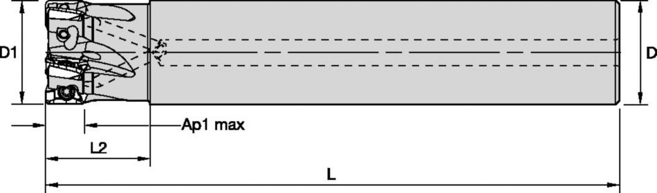
Przykłady zastosowania
| Mill 1-7™ • Ramping Angles [mm] | ||||
| cutting diameter | max ramp angle to non-cutting corner tangent | DH min (min hole diameter) | DHI min (min flat-bottomed hole diameter) | max diameter (no flat bottom) |
| 12 | 5,49° | 14,62 | 21,43 | 24 |
| 16 | 2,92° | 22,52 | 28,04 | 32 |
| 20 | 2,01° | 30,51 | 36,49 | 40 |
| Mill 1-7 | |
| max ADOC | 6,98 |
| fz | 0,10–0,68 |
| hm | 0,09 |
Application Examples
| Mill 1-7 | |
| max ADOC | .275 |
| fz | .004–.027 |
| hm | .003 |
| Mill 1-7™ • Ramping Angles [Inch] | ||||
| cutting diameter | max ramp angle to non-cutting corner tangent | DH min (min hole diameter) | DHI min (min flat-bottomed hole diameter) | max diameter (no flat bottom) |
| .500 | 4.56° | .628 | .886 | 1.000 |
| .625 | 2.97° | .877 | 1.095 | 1.250 |
| .750 | 2.17° | 1.126 | 1.362 | 1.500 |
| cutting diameter | max ramp angle to non-cutting corner tangent | DH min (min hole diameter) | DHI min (min flat-bottomed hole diameter) | max diameter (no flat bottom) |
| 12 | 5,49° | 14,62 | 21,43 | 24 |
| 16 | 2,92° | 22,52 | 28,04 | 32 |
| 20 | 2,01° | 30,51 | 36,49 | 40 |