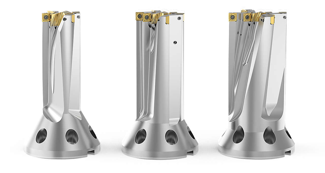
Wiertło FBX
Wiertła modułowe do otworów z płaskim dnem


Wiertło FBX to idealne rozwiązanie do obróbki wstępnej części konstrukcyjnych ze stopów żarowytrzymałych.
4 duże rowki wiórowe i 4 efektywne krawędzie skrawające na zewnętrznej średnicy narzędzia gwarantują szybkie usuwanie materiału na dużych metalowych płytach lub elementach kutych.
Płytka centralna z 2 efektywnymi krawędziami skrawającymi i łamaczami wiórów umożliwia doskonałe formowanie wiórów, co zapewnia możliwość stosowania maksymalnych wartości posuwu.
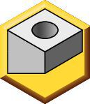
Konstrukcja wierzchołka wiertła o płaskim dnie eliminuje siły promieniowe. Idealne rozwiązanie do zastosowań w maszynach o niższej mocy.
Kołnierz ze stożkiem śrubowym (BTF) zapewnia maksymalną sztywność narzędzia.
Niemal tak sztywne narzędzie jak konstrukcja monoblokowa, ale oferujące wiele innych połączeń z maszynami.

Korpusy wiertła FBX o długości 95 mm — średnice 60, 75, 90 mm
Korpusy wiertła FBX o długości 150 mm — średnice 60, 75, 90 mm
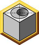
Geometria wierzchołka wiertła o płaskim dnie. Frezowanie wgłębne o najwyższej wydajności z wykorzystaniem 4 efektywnych krawędzi skrawających na zewnętrznej średnicy
Płytki wymienne z 4 krawędziami skrawającymi zapewniają niskie koszty na krawędź skrawającą.
Regulowane dysze chłodziwa zapewniają wydajne zarządzanie ciepłem.
Płytka centralna z 2 efektywnymi krawędziami skrawającymi i z łamaczami wiórów dla maksymalnego posuwu
Cztery rowki wiórowe zapewniają bezproblemowe odprowadzanie wiórów i maksymalną stabilność podczas ciągłego wiercenia otworów.
Kołnierz ze stożkiem śrubowym (BTF) zapewnia maksymalną sztywność narzędzia.
Niemal tak sztywne narzędzie jak konstrukcja monoblokowa, ale oferujące wiele innych połączeń z maszynami.
Narzędzia z kołnierzem ze stożkiem śrubowym zapewniają maksymalną elastyczność dzięki standardowym rodzajom połączeń KM4X, HSK, DV, CV i BT.
Surowa płytka tytanowa
Otwieranie wgłębień
(Wiertła modułowe do otworów z płaskim dnem)
Obróbka zgrubna
Obróbka wykańczająca
(monolityczne frezy trzpieniowe)
 Chain Drilling
(6)
Chain Drilling
(6)
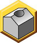
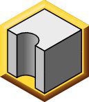
 Convex Drilling
(6)
Convex Drilling
(6)
 Corner Drilling 45°
(6)
Corner Drilling 45°
(6)
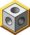 Cross Hole Drilling
(6)
Cross Hole Drilling
(6)
 Drilling
(6)
Drilling
(6)
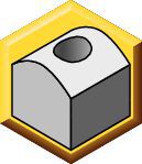
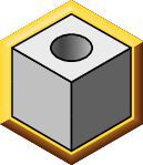
 Flat Bottom Drilling
(6)
Flat Bottom Drilling
(6)
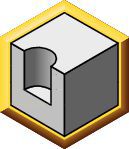
 Half Cylindrical Drilling
(6)
Half Cylindrical Drilling
(6)
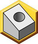 Inclined Entry Drilling
(6)
Inclined Entry Drilling
(6)
 Inclined Exit Drilling
(6)
Inclined Exit Drilling
(6)
 X-Offset Drilling
(6)
X-Offset Drilling
(6)
Oznaczenie katalogowe ISO
Oznaczenie katalogowe ANSI
to find similar products.Models
. Please enter the desired qty for the material(s) you want to include in your promotion or Proceed Without Promotion and only your base materials will be added to the cart.
Minimum quantity should be
| SAP Material Number | Oznaczenie katalogowe ISO | Gatunek |
|---|
Thank you for your registration, pending approval & completion of the registration, your access is currently limited. Full utilization of product search capabilities & collaboration space is available and will remain. Please allow 2 business days for registration completion.
Dziękujemy za pomyślną rejestrację. Możesz teraz zalogować się i korzystać z witryny
You are about to leave the Solution building process.
Are you sure you want to leave?


