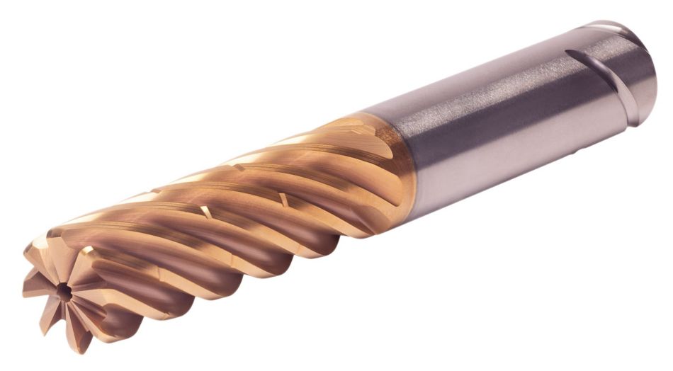

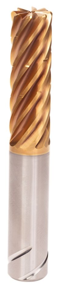
HARVI™ IV • Radiused • 8 Flutes • Internal Coolant • Chipbreaker • Safe LockTM Shank • Inch
HARVI™ IV Eight Flute End Mill for Roughing and Finishing
Covering the Broadest Range of Applications and Materials
Özellikler ve avantajlar
- "Single tool for roughing and finishing to reduce tool setups.
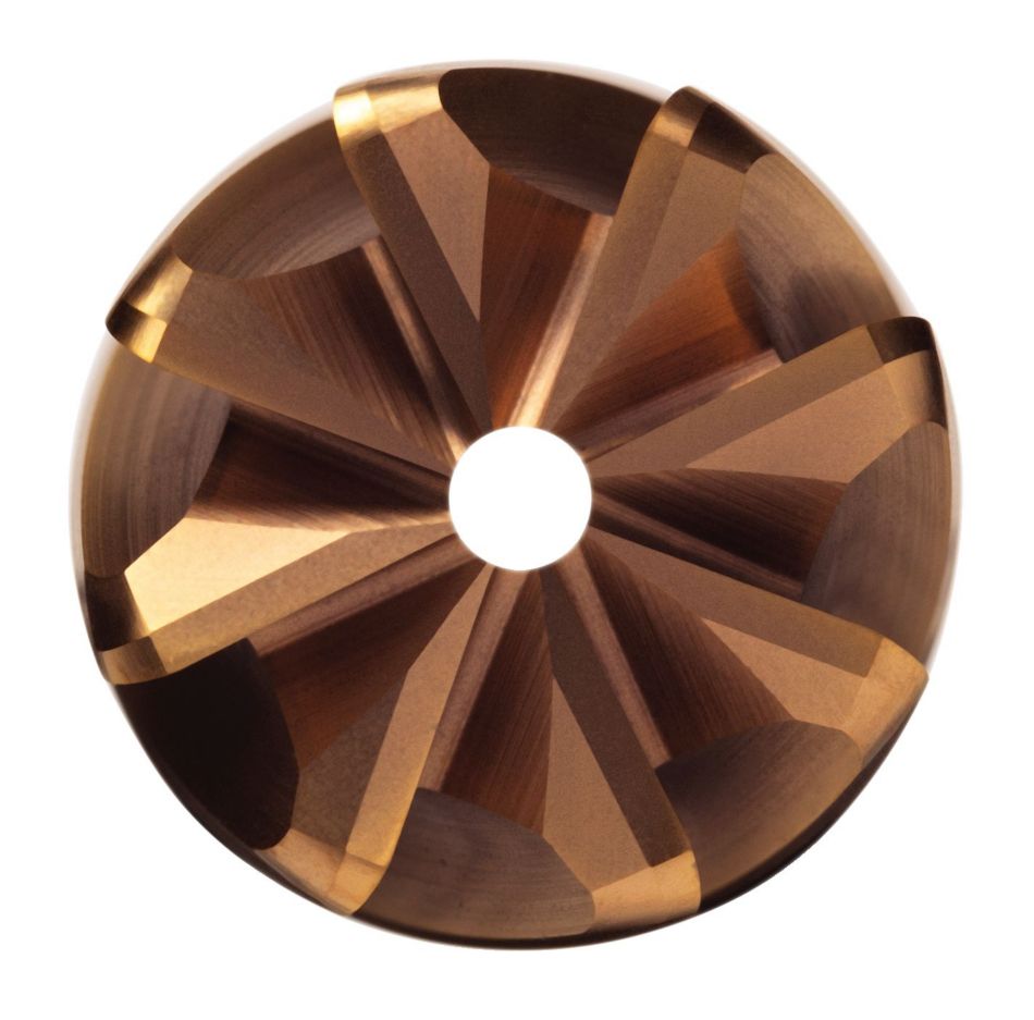
- Proprietary core and flute design with optimum flute spacing for perfect chip formation and highest tool rigidity.
- Developed for highest productivity in titanium, high-temperature alloys, and stainless steels.
- With chip breakers for optimized chip evacuation.
- With Safe-Lock for pull-out protection."
Kullanım ve uygulama alanları
Trochoidal Milling
100665610
107038547
Helical Milling
Ramping: Blank
Side Milling/Shoulder Milling: Square End
Pocketing
 <="" td="" />
 <="" td="">