Bienvenue
Veuillez confirmer vos préférences
Mettre à jour les préférences
Suggestions de produit
Product Family suggestions
Kennametal à votre service
Support Clients
Nouveau client
Êtes-vous un nouveau client de Kennametal ? Créez un compte et commencez.
Créer un compteBonjour, User Name
Votre compte sélectionné :
Il y a un problème avec votre compte. Veuillez contacter le service client.
Compte Client
Modifier le compte
Compte de livraison
Modifier le compte
- Tableau de bord
- Gérer les commandes
- Gérer les canaux
- Carnet d’adresses
-
Notifications
Mark all as read - Modifier le mot de passe
- Mon profil
- Se déconnecter
Article(s)
ajoutées avec succès au panier
Voir le panier
Voir le panier
Usinez plus pour moins cher avec nos promotions!
Achetez maintenant
Kennametal à votre service
Support Clients
Article(s)
ajoutées avec succès au panier
Voir le panier
Voir le panier
Édition de la Solution
Ajout de Solution
Nom de la Solution: {{SolutionName}}- Produits
- /
- Outils d’usinage des métaux
- /
- Fraisage
- /
- Fraisage indexable
- /
- Fraises céramique
- /
- Ceramic Mills • RN
- /
- KCRA • RN
- /
- KCRA - RN • Fraises à queue cylindriques • Métrique
Sending to SolidCAM in progress...
Downloaded file will be available after import in the SolidCAM tool library.
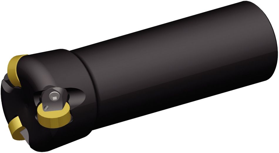
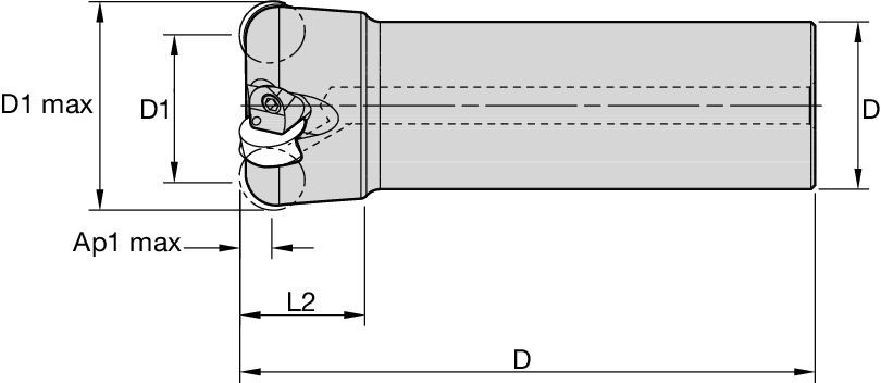
KCRA - RN • Fraises à queue cylindriques • Métrique
Fraises à queue cylindrique
Features and benefits
- Premier choix pour le surfaçage et le surfaçage-dressage des alliages hautes températures.
- Débit-copeau supérieur grâce aux fraises à pas fin.
- Le système de fixation sûr améliore la fiabilité et la stabilité du processus.
- Fonction de refroidissement par air efficace. Meilleure évacuation des copeaux et tenue de coupe prolongée.
Uses and application
Milling - Pressurized Air Coolant
Surfaçage
Fraisage de côté/avec épaulement : Bout hémisphérique
Queue — Cylindrique Classique
| Material Group | Light
|
General
|
Heavy
|
|||
| – | (Light geometry) | – | (Strong geometry) | |||
| – | wear
|
 <="" td=""> <="" td=""> | toughness | |||
| – | Geometry | Grade | Geometry | Grade | Geometry | Grade |
| P1–P2 | – | – | – | – | – | – |
| P3–P4 | – | – | – | – | – | – |
| P5–P6 | – | – | – | – | – | – |
| M1–M2 | – | – | – | – | – | – |
| M3 | – | – | – | – | – | – |
| K1–K2 | – | – | – | – | – | – |
| K3 | – | – | – | – | – | – |
| N1–N2 | – | – | – | – | – | – |
| N3 | – | – | – | – | – | – |
| S1–S2 | .EGN | KYS30 | .EGN | KYS30 | .TGN | KYS30 |
| S3 | .EGN | KYSP30 | .EGN | KYSP30 | .TGN | KYSP30 |
| S4 | – | – | – | – | – | – |
| H1 | – | – | – | – | – | – |
À une profondeur de coupe axiale (ap) de 6,35
| Insert Geometry | Recommended Starting Feed per Tooth (Fz) in Relation to % of Radial Engagement (ae) | Insert Geometry | ||||||||||||||
| 10% | 20% | 30% | 40% | 50–100% | ||||||||||||
| .EGN | 0,08 | 0,09 | 0,11 | 0,06 | 0,07 | 0,09 | 0,06 | 0,06 | 0,07 | 0,05 | 0,06 | 0,07 | 0,05 | 0,06 | 0,07 | .EGN |
| .TGN | 0,13 | 0,17 | 0,19 | 0,09 | 0,13 | 0,14 | 0,08 | 0,11 | 0,13 | 0,08 | 0,10 | 0,12 | 0,08 | 0,10 | 0,12 | .TGN |
À une profondeur de coupe axiale (ap) de 3,00
| Light
|
General
|
Heavy
|
À une profondeur de coupe axiale (ap) de 1,50
| Insert Geometry | Recommended Starting Feed per Tooth (Fz) in Relation to % of Radial Engagement (ae) | Insert Geometry | ||||||||||||||
| 10% | 20% | 30% | 40% | 50–100% | ||||||||||||
| .EGN | 0,18 | 0,20 | 0,24 | 0,13 | 0,15 | 0,18 | 0,12 | 0,13 | 0,16 | 0,11 | 0,12 | 0,15 | 0,11 | 0,12 | 0,14 | .EGN |
| .TGN | 0,27 | 0,36 | 0,41 | 0,20 | 0,27 | 0,31 | 0,17 | 0,23 | 0,27 | 0,16 | 0,22 | 0,25 | 0,16 | 0,21 | 0,24 | .TGN |
À une profondeur de coupe axiale (ap) de 0,75
| Insert Geometry | Recommended Starting Feed per Tooth (Fz) in Relation to % of Radial Engagement (ae) | Insert Geometry | ||||||||||||||
| 10% | 20% | 30% | 40% | 50–100% | ||||||||||||
| .EGN | 0,10 | 0,11 | 0,13 | 0,07 | 0,08 | 0,10 | 0,07 | 0,07 | 0,09 | 0,06 | 0,07 | 0,08 | 0,06 | 0,07 | 0,08 | .EGN |
| .TGN | 0,15 | 0,20 | 0,23 | 0,11 | 0,15 | 0,17 | 0,10 | 0,13 | 0,15 | 0,09 | 0,12 | 0,14 | 0,09 | 0,12 | 0,14 | .TGN |
| Insert Geometry | Recommended Starting Feed per Tooth (Fz) in Relation to % of Radial Engagement (ae) | Insert Geometry | ||||||||||||||
| 10% | 20% | 30% | 40% | 50–100% | ||||||||||||
| .EGN | 0,13 | 0,14 | 0,18 | 0,10 | 0,11 | 0,13 | 0,09 | 0,09 | 0,12 | 0,08 | 0,09 | 0,11 | 0,08 | 0,09 | 0,11 | .EGN |
| .TGN | 0,19 | 0,26 | 0,30 | 0,15 | 0,19 | 0,22 | 0,13 | 0,17 | 0,19 | 0,12 | 0,16 | 0,18 | 0,12 | 0,15 | 0,18 | .TGN |
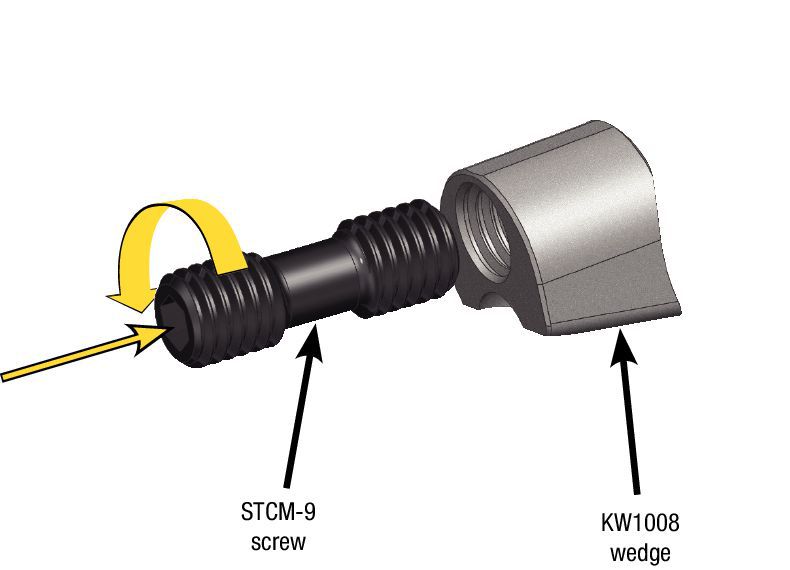
Guide de montage des plaquettes
| Safety Notes | |||||
 <="" td=""> <="" td=""> |  <="" td=""> <="" td=""> | 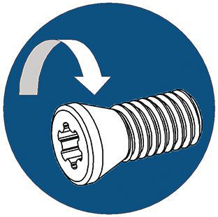 <="" td=""> <="" td=""> |  <="" td=""> <="" td=""> |  <="" td=""> <="" td=""> |  <="" td="" /> <="" td="" /> |
| Read all instructions carefully | Wear eye protection | Inspect and tighten fasteners regularly | Warning: Cutting hazard | Warning: Hot surfaces | Do not exceed maximum RPM |
| Assembly Instructions | |
| Assemble STCM-25 screw to KW1008 wedge, 1 to 1 1/2 turns. | Wedge/screw assembly. |
 <="" td=""> <="" td=""> |  <="" td="" /> <="" td="" /> |
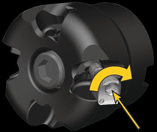
| Install wedge/screw assembly into cutter body, but maintain assembly gap for installing insert. | Slide insert, RNGN12... into pocket and torque wedge/insert assembly to 3,5 Nm (31 in/lbs). Repeat for each pocket. |
 <="" td=""> <="" td=""> | 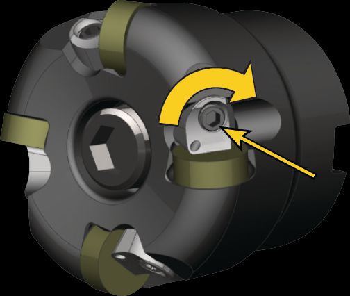 <="" td="" /> <="" td="" /> |
Vitesses de départ recommandées [m/mn]
| Material Group | KYS30 | KYSP30 | |||||
| P | 1 | – | – | – | – | – | – |
| 2 | – | – | – | – | – | – | |
| 3 | – | – | – | – | – | – | |
| 4 | – | – | – | – | – | – | |
| 5 | – | – | – | – | – | – | |
| 6 | – | – | – | – | – | – | |
| M | 1 | – | – | – | – | – | – |
| 2 | – | – | – | – | – | – | |
| 3 | – | – | – | – | – | – | |
| K | 1 | – | – | – | – | – | – |
| 2 | – | – | – | – | – | – | |
| 3 | – | – | – | – | – | – | |
| N | 1 | – | – | – | – | – | – |
| 2 | – | – | – | – | – | – | |
| S | 1 | 805 | 660 | 510 | 805 | 660 | 510 |
| 2 | 805 | 660 | 510 | 805 | 660 | 510 | |
| 3 | 1170 | 950 | 730 | 1170 | 950 | 730 | |
| 4 | – | – | – | – | – | – | |
| H | 1 | – | – | – | – | – | – |
| 2 | – | – | – | – | – | – | |
| 3 | – | – | – | – | – | – | |