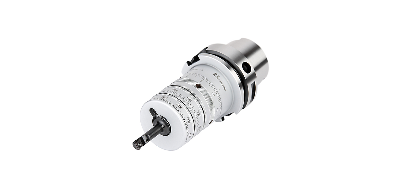
Ferramental SVUBB para diâmetros de 4 a 100 mm (0,157 a 3,937 pol.).
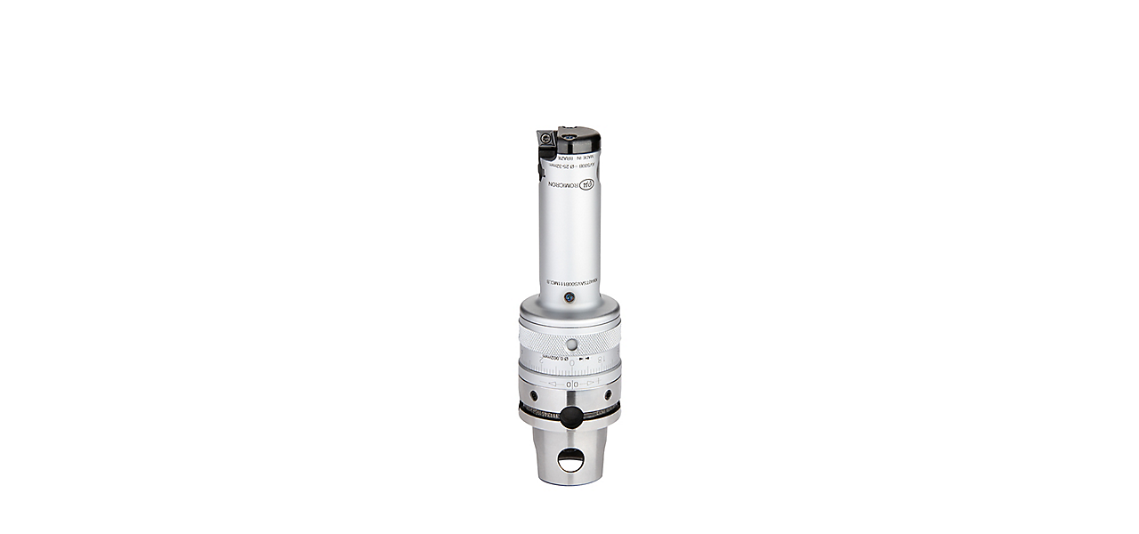
Cabeças pré-balanceadas AVS para diâmetros de 25 a 79 mm (0,984 a 3,11 pol.).
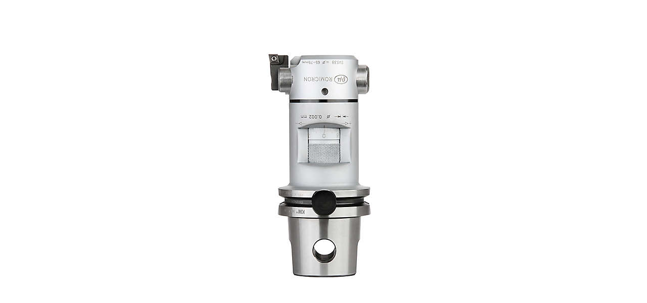
Cabeças pré-balanceadas SVS para diâmetros de 78 a 139 mm (3,07 a 5,472 pol.). Somente para ajuste manual.
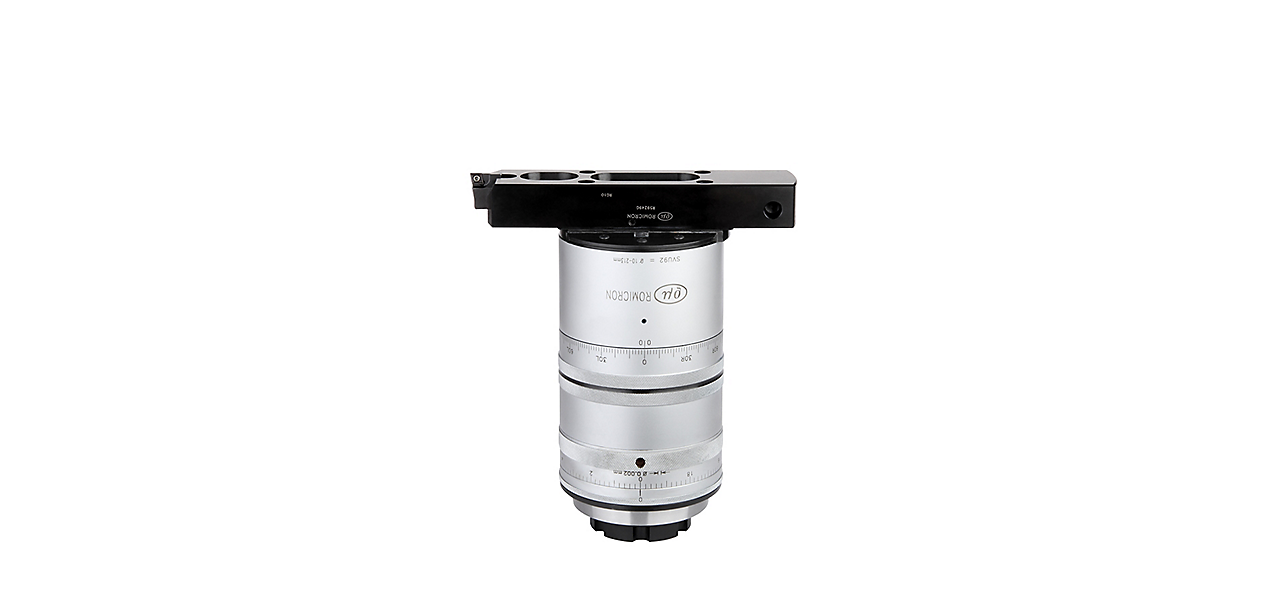
Ferramental SVU para diâmetros maiores, entre 71 e 213 mm (2,79 a 8,386 pol.).
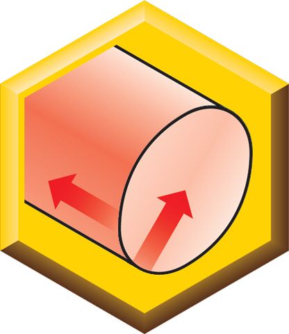
Aumente a produtividade e a performance em aplicações de mandrilamento fino
Sistema de alta precisão para produção de grande volume, nas quais são necessárias aplicações de mandrilamento fino totalmente automatizadas e com baixíssima tolerância.
Ao abranger um intervalo de diâmetro de 4 a 213 mm (0,1575 a 8,3858 pol.), o Romicron apresenta uma precisão de furo de até IT6, cilindricidade de furo de até 5 μm e posição de furo de até 5 μm.
Aplicável em qualquer material, o Romicron reduz o tempo de configuração e as taxas de refugos, aumentando a produtividade geral e a eficiência do equipamento.
As máquinas existentes podem ser facilmente adaptadas para compensação automatizada de desgaste do inserto utilizando o pino padrão de mandrilamento para ajuste de medida.
Ao usar um apalpador, é possível eliminar cortes de controle demorados, ferramental similar caro ou trocas de insertos na área de pré-configuração.
O ajuste do diâmetro pode ser feito dentro da máquina.