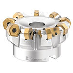
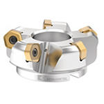
Fresamento de face com 12 arestas de corte efetivas por inserto

  • As plataformas de fresamento de face Dodeka, Dodeka Mini e Dodeka MAX™ são as impulsionadoras de fresamento de face mais abrangentes do mercado atualmente.
  • Doze arestas de corte efetivas por inserto significam baixo custo por aresta e alta produtividade.
  • Com as classes especiais de fresamento Beyond™, alcance um aumento de até 30% nas taxas de remoção de material (MRR), diminuição de até 25% nas forças de corte inferiores devido à efetiva ação de corte macio e aumento de até 35% da vida útil da ferramenta em usinagens pesadas ou leves.
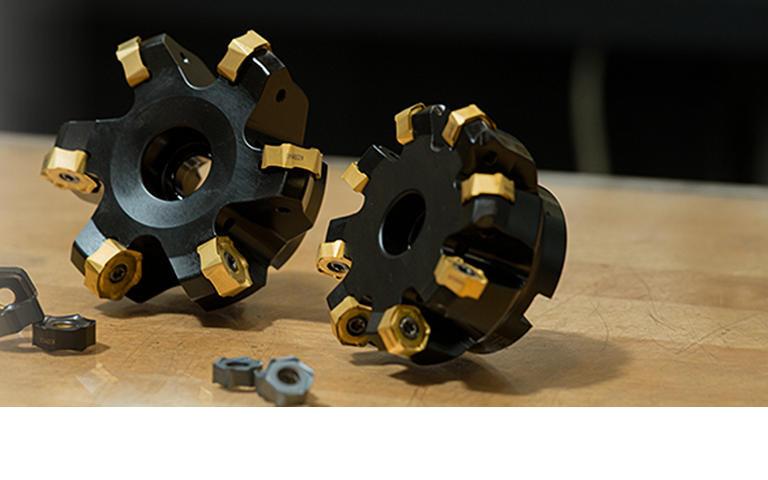
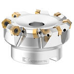
Novos insertos de geometria de alta posição

Para Dodeka e Dodeka Mini

Geometria LM

  • Inserto de fresamento para usinagem leve de materiais de aço inoxidável.
  • Excelente formação de cavacos e acabamento da superfície melhorado.
  • Ação de corte suave exigindo menos potência do fuso.
  • Geometria do inserto superpositiva sem vibração por ressonância.

Geometria LP

  • Inserto de fresamento para usinagem leve de aços.
  • Excelente formação de cavacos e acabamento da superfície melhorado.
  • Ação de corte suave exigindo menos potência do fuso.
  • Geometria do inserto superpositiva sem vibração por ressonância.

Geometria GM

  • Primeira opção para desbaste médio de materiais de aço inoxidável.
  • Excelente acabamento superficial para pisos.
  • Ação de corte suave exigindo menos potência do fuso.
  • Geometria do inserto superpositiva sem vibração por ressonância.

Geometria GP

  • Primeira opção para desbaste médio de aços.
  • Excelente acabamento superficial para pisos.
  • Ação de corte suave exigindo menos potência do fuso.
  • Geometria do inserto superpositiva sem vibração por ressonância.

Características e benefícios

  • Doze arestas de corte efetivas por inserto
  • Baixas forças de corte, ação de corte suave
  • Melhor formação e evacuação de cavacos
  • As melhores combinações de geometria de inserto/classe para aço usinável, aço inoxidável e ligas resistentes a altas temperaturas
  • Excelente acabamento do piso
  • Capacidades de usinagem elevadas
  • Novas geometrias altamente positivas
Selecionar filtros
Filtros
Exibir filtros em
Métrico
Polegada
keyFilters
Workpiece Material
Workpiece Material
  • P Steel (282)
    • P0
      Low-Carbon Steels, Long Chipping C < .25%; <125 HB; <530 N/mm^2 UTS (260)
    • P1
      Low-Carbon Steels, Short Chipping C < .25%; <125 HB; <530 N/mm^2 UTS (260)
    • P2
      Medium and High Carbon Steels C < .25%; <220 HB; <25 HRC; >530 N/mm^2 UTS (260)
    • P3
      Alloy Steels & Tool Steels C > .25%; <330 HB; <35 HRC; 600-850 N/mm^2 UTS (260)
    • P4
      Alloy Steels & Tool Steels C > .25%; 350-420 HB; 35-43 HRC; 850-1400 N/mm^2 UTS (264)
    • P5
      Ferritic, Martensitic, and PH Stainless Steels <330 HB; <35 HRC; 600-900 N/mm^2 UTS (278)
    • P6
      High Strength Ferritic, Martensitic, and PH Stainless Steels 350-450 HB; 35-43 HRC; 900-2400 N/mm^2 UTS (278)
  • M Stainless Steel (268)
    • M1
      Austenitic Stainless Steel 130-200 HB; <600 N/mm^2 UTS (268)
    • M2
      High Strength Austenitic Stainless and Cast Stainless Steels 150-230 HB; <25 HRC; >600 N/mm^2 UTS (268)
    • M3
      Duplex Stainless Steel 135-275 HB; <30 HRC; 500-1200 N/mm^2 UTS (268)
  • K Cast Iron (253)
    • K1
      Gray Cast Iron 120-290 HB; <32 HRC; 125-500 N/mm^2 UTS (253)
    • K2
      Low and Medium Strength CGI and Ductile Irons 130-260 HB; <28 HRC; <600 N/mm^2 UTS (252)
    • K3
      High Strength Ductile and Austempered Ductile Iron 180-350 HB; <43 HRC; >600 N/mm^2 UTS (252)
  • N Non-Ferrous Materials (147)
    • N1
      Wrought Aluminum (147)
    • N2
      Low-Silicon Aluminum Alloys and Magnesium Alloys Si <12.2% (146)
    • N3
      High-Silicon Aluminum Alloys Si >12.2% (146)
    • N4
      Copper, Brass, Zinc-based on machinability index range of 70-100 (94)
  • S High-Temp Alloys (262)
    • S1
      Iron-Based, Heat-Resistant Alloys 160-260 HB; 25-48 HRC; 500-1200 N/mm^2 UTS (242)
    • S2
      Cobalt-Based, Heat-Resistant Alloys 250-450 HB; 25-48 HRC; 1000-1450 N/mm^2 UTS (242)
    • S3
      Nickel-Based, Heat Resistant Alloys 160-450 HB; <48 HRC; 600-1700 N/mm^2 UTS (242)
    • S4
      Titanium and Titanium Alloys 300-400 HB; 33-43 HRC; 900-1600 N/mm^2 UTS (262)
  • H Hardened Materials (179)
    • H1
      Hardened Materials 44-48 HRC (179)
Selecione First Choice
  • BR (32)
  • CN (102)
  • DE (115)
  • GB (72)
  • IN (42)
  • SG (54)
  • US (114)
Applications
Applications
  • Chamfer Milling Chamfer Milling (141)
  • Face Milling Face Milling (168)
Cutting Diameter
Cutting Diameter
  • 0.984 in (7)
  • 1.0 in (7)
  • 1.25 in (7)
  • 1.26 in (8)
  • 1.5 in (5)
  • 1.575 in (10)
  • 1.969 in (9)
  • 2.0 in (9)
  • 2.48 in (10)
  • 2.5 in (9)
  • 3.0 in (11)
  • 3.15 in (11)
  • 3.938 in (10)
  • 4.0 in (9)
  • 4.921 in (10)
  • 5.0 in (10)
  • 6.0 in (5)
  • 6.299 in (5)
  • 7.875 in (3)
  • 8.0 in (2)
  • 9.843 in (3)
  • 10.0 in (3)
  • 12.0 in (2)
  • 12.403 in (3)
Cutting Diameter Min a Cutting Diameter Max
Cutting Diameter
Cutting Diameter
  • 25.0 mm (7)
  • 25.401 mm (7)
  • 31.75 mm (7)
  • 32.0 mm (8)
  • 38.1 mm (5)
  • 40.0 mm (10)
  • 50.0 mm (9)
  • 50.801 mm (9)
  • 63.0 mm (10)
  • 63.5 mm (9)
  • 76.2 mm (11)
  • 80.0 mm (11)
  • 100.0 mm (10)
  • 101.601 mm (9)
  • 125.0 mm (10)
  • 127.0 mm (10)
  • 152.4 mm (5)
  • 160.0 mm (5)
  • 200.0 mm (3)
  • 203.201 mm (2)
  • 250.0 mm (3)
  • 254.0 mm (3)
  • 304.8 mm (2)
  • 315.0 mm (3)
Cutting Diameter Min a Cutting Diameter Max
Maximum Cutting Diameter
  • 33.176 mm (5)
  • 33.575 mm (5)
  • 38.15 mm (2)
  • 38.551 mm (2)
  • 39.926 mm (6)
  • 40.176 mm (6)
  • 44.45 mm (2)
  • 44.901 mm (1)
  • 45.151 mm (2)
  • 46.276 mm (2)
  • 46.35 mm (2)
  • 48.176 mm (2)
  • 51.0 mm (5)
  • 51.25 mm (1)
  • 53.151 mm (1)
  • 56.35 mm (2)
  • 57.151 mm (2)
  • 58.151 mm (3)
  • 58.95 mm (3)
  • 61.0 mm (2)
  • 61.801 mm (2)
  • 63.151 mm (1)
  • 63.95 mm (1)
  • 67.9 mm (1)
  • 69.351 mm (2)
  • 69.75 mm (1)
  • 69.851 mm (1)
  • 71.15 mm (3)
  • 71.65 mm (3)
  • 74.0 mm (3)
  • 74.5 mm (3)
  • 76.15 mm (1)
  • 76.65 mm (1)
  • 80.875 mm (1)
  • 82.45 mm (1)
  • 82.551 mm (2)
  • 84.351 mm (3)
  • 86.325 mm (2)
  • 87.2 mm (3)
  • 88.15 mm (3)
  • 89.325 mm (1)
  • 91.0 mm (3)
  • 93.125 mm (1)
  • 93.525 mm (1)
  • 95.15 mm (1)
  • 97.325 mm (1)
  • 97.875 mm (1)
  • 106.325 mm (2)
  • 107.5 mm (1)
  • 107.926 mm (1)
  • 108.15 mm (3)
  • 109.75 mm (3)
  • 110.976 mm (3)
  • 112.575 mm (2)
  • 117.325 mm (1)
  • 117.851 mm (1)
  • 118.926 mm (1)
  • 120.525 mm (1)
  • 131.326 mm (2)
  • 133.15 mm (3)
  • 133.326 mm (2)
  • 135.15 mm (3)
  • 135.951 mm (2)
  • 135.975 mm (1)
  • 137.951 mm (3)
  • 142.326 mm (1)
  • 142.875 mm (1)
  • 144.326 mm (1)
  • 145.951 mm (1)
  • 163.375 mm (3)
  • 169.726 mm (1)
  • 170.976 mm (3)
  • 171.4 mm (1)
  • 177.326 mm (1)
  • 177.951 mm (1)
  • 211.0 mm (1)
  • 214.175 mm (1)
  • 217.326 mm (2)
  • 220.5 mm (1)
  • 261.0 mm (1)
  • 265.0 mm (1)
  • 267.3 mm (2)
  • 271.3 mm (2)
  • 315.8 mm (1)
  • 322.1 mm (1)
  • 326.0 mm (1)
  • 332.3 mm (2)
Maximum Cutting Diameter Min a Maximum Cutting Diameter Max
Maximum Cutting Diameter
  • 1.306 in (5)
  • 1.322 in (5)
  • 1.502 in (2)
  • 1.518 in (2)
  • 1.572 in (6)
  • 1.582 in (6)
  • 1.75 in (2)
  • 1.768 in (1)
  • 1.778 in (2)
  • 1.822 in (2)
  • 1.825 in (2)
  • 1.897 in (2)
  • 2.008 in (5)
  • 2.019 in (1)
  • 2.093 in (1)
  • 2.219 in (2)
  • 2.25 in (2)
  • 2.289 in (3)
  • 2.321 in (3)
  • 2.402 in (2)
  • 2.433 in (2)
  • 2.486 in (1)
  • 2.519 in (1)
  • 2.673 in (1)
  • 2.73 in (2)
  • 2.746 in (1)
  • 2.75 in (1)
  • 2.801 in (3)
  • 2.821 in (3)
  • 2.914 in (3)
  • 2.934 in (3)
  • 2.998 in (1)
  • 3.019 in (1)
  • 3.184 in (1)
  • 3.246 in (1)
  • 3.25 in (2)
  • 3.321 in (3)
  • 3.399 in (2)
  • 3.434 in (3)
  • 3.47 in (3)
  • 3.517 in (1)
  • 3.583 in (3)
  • 3.666 in (1)
  • 3.682 in (1)
  • 3.746 in (1)
  • 3.833 in (1)
  • 3.853 in (1)
  • 4.186 in (2)
  • 4.232 in (1)
  • 4.249 in (1)
  • 4.258 in (3)
  • 4.321 in (3)
  • 4.369 in (3)
  • 4.432 in (2)
  • 4.619 in (1)
  • 4.64 in (1)
  • 4.682 in (1)
  • 4.745 in (1)
  • 5.17 in (2)
  • 5.242 in (3)
  • 5.249 in (2)
  • 5.321 in (3)
  • 5.352 in (2)
  • 5.353 in (1)
  • 5.431 in (3)
  • 5.603 in (1)
  • 5.625 in (1)
  • 5.682 in (1)
  • 5.746 in (1)
  • 6.432 in (3)
  • 6.682 in (1)
  • 6.731 in (3)
  • 6.748 in (1)
  • 6.981 in (1)
  • 7.006 in (1)
  • 8.307 in (1)
  • 8.432 in (1)
  • 8.557 in (2)
  • 8.682 in (1)
  • 10.276 in (1)
  • 10.433 in (1)
  • 10.525 in (2)
  • 10.682 in (2)
  • 12.433 in (1)
  • 12.682 in (1)
  • 12.835 in (1)
  • 13.083 in (2)
Maximum Cutting Diameter Min a Maximum Cutting Diameter Max
Cutting Length
Cutting Length
  • 1.625 mm (10)
  • 1.651 mm (5)
  • 2.2 mm (12)
  • 3.2 mm (12)
  • 3.225 mm (44)
  • 4.3 mm (22)
  • 4.476 mm (2)
  • 4.5 mm (43)
  • 8.0 mm (18)
Cutting Length Min a Cutting Length Max
Cutting Length
Cutting Length
  • 0.064 in (10)
  • 0.065 in (5)
  • 0.088 in (12)
  • 0.126 in (12)
  • 0.127 in (44)
  • 0.169 in (22)
  • 0.176 in (2)
  • 0.177 in (43)
  • 0.315 in (18)
Cutting Length Min a Cutting Length Max
Reach
Reach
  • 1.25 in (7)
  • 1.26 in (7)
  • 1.5 in (7)
  • 1.57 in (5)
  • 1.575 in (49)
  • 1.594 in (2)
  • 1.75 in (18)
  • 1.77 in (2)
  • 1.969 in (25)
  • 2.375 in (5)
  • 2.38 in (13)
  • 2.402 in (2)
  • 2.48 in (21)
  • 3.15 in (5)
Reach Min a Reach Max
Reach
Reach
  • 31.75 mm (7)
  • 32.0 mm (7)
  • 38.1 mm (7)
  • 39.875 mm (5)
  • 40.0 mm (49)
  • 40.5 mm (2)
  • 44.45 mm (18)
  • 44.95 mm (2)
  • 50.0 mm (25)
  • 60.325 mm (5)
  • 60.45 mm (13)
  • 60.975 mm (2)
  • 63.0 mm (21)
  • 80.0 mm (5)
Reach Min a Reach Max
Tool Cutting Edge Angle
  • 15.0 (27)
  • 45.0 (119)
  • 58.0 (22)
Tool Cutting Edge Angle Min a Tool Cutting Edge Angle Max
Connection Style
Connection Style
  • A-Socket Head Cap Screw (100)
  • B-Cutter Retention Screw (11)
  • C-Bolt Circle (16)
  • KL Screw (3)
  • SHCS or RetScrw Or BoltCircle (5)
  • Screw-On Connection (7)
  • Straight-Cylindrical (17)
  • Weldon (9)
Number of Flutes
Number of Flutes
  • 10 (7)
  • 11 (2)
  • 12 (14)
  • 14 (5)
  • 16 (6)
  • 18 (2)
  • 2 (4)
  • 20 (2)
  • 24 (2)
  • 3 (19)
  • 4 (28)
  • 5 (26)
  • 6 (22)
  • 7 (2)
  • 8 (18)
  • 9 (9)
Cutting Edges Per Insert
  • 6.0 (112)
  • 12.0 (301)
Cutting Edges Per Insert Min a Cutting Edges Per Insert Max
Internal Coolant Capability
Over All Length [L]
Over All Length [L]
  • 1.57 in (5)
  • 1.575 in (41)
  • 1.594 in (2)
  • 1.75 in (18)
  • 1.77 in (2)
  • 1.969 in (21)
  • 2.224 in (2)
  • 2.375 in (5)
  • 2.38 in (13)
  • 2.402 in (2)
  • 2.465 in (2)
  • 2.48 in (21)
  • 2.539 in (3)
  • 3.15 in (5)
  • 3.228 in (1)
  • 3.281 in (2)
  • 3.781 in (2)
  • 3.819 in (2)
  • 4.213 in (4)
  • 4.724 in (3)
  • 4.799 in (2)
  • 4.8 in (2)
  • 5.118 in (3)
  • 5.2 in (1)
  • 5.202 in (2)
  • 7.875 in (1)
  • 8.0 in (1)
Over All Length [L] Min a Over All Length [L] Max
Over All Length [L]
Over All Length [L]
  • 39.875 mm (5)
  • 40.0 mm (41)
  • 40.5 mm (2)
  • 44.45 mm (18)
  • 44.95 mm (2)
  • 50.0 mm (21)
  • 56.5 mm (2)
  • 60.325 mm (5)
  • 60.45 mm (13)
  • 60.975 mm (2)
  • 62.6 mm (2)
  • 63.0 mm (21)
  • 64.5 mm (3)
  • 80.0 mm (5)
  • 82.0 mm (1)
  • 83.301 mm (2)
  • 96.0 mm (2)
  • 97.0 mm (2)
  • 107.0 mm (4)
  • 120.0 mm (3)
  • 121.9 mm (2)
  • 121.926 mm (2)
  • 130.0 mm (3)
  • 132.076 mm (1)
  • 132.1 mm (2)
  • 200.0 mm (1)
  • 203.201 mm (1)
Over All Length [L] Min a Over All Length [L] Max
cornerConfiguration
Corner Radius
Corner Radius
  • 0.039 in (138)
  • 0.047 in (190)
  • 0.063 in (112)
  • 0.079 in (25)
  • 0.126 in (100)
  • 0.138 in (20)
  • 0.171 in (70)
Corner Radius Min a Corner Radius Max
Corner Radius
Corner Radius
  • 1.0 mm (138)
  • 1.201 mm (190)
  • 1.6 mm (112)
  • 2.0 mm (25)
  • 3.2 mm (100)
  • 3.5 mm (20)
  • 4.351 mm (70)
Corner Radius Min a Corner Radius Max
application
Grade Of Cutting Tool
  • K313 (94)
  • KC410M (142)
  • KC510M (95)
  • KC520M (176)
  • KC522M (168)
  • KC725M (185)
  • KCK15 (184)
  • KCK20B (160)
  • KCKP10 (95)
  • KCMP30 (93)
  • KCPK30 (188)
  • KCPM20 (156)
  • KCPM40 (187)
  • KCSM30 (151)
  • KCSM40 (186)
  • KTPK20 (57)
  • KY3500 (58)
  • KYS30 (57)
Hand Of Tool
Hand Of Tool
  • R (168)
Wiper Insert
Wiper Insert
  • N (119)
  • Y (25)
frontEnd
Neck Diameter
Neck Diameter
  • 0.76 in (3)
  • 0.946 in (1)
  • 0.958 in (3)
  • 0.965 in (1)
  • 1.006 in (6)
  • 1.059 in (1)
  • 1.256 in (11)
Neck Diameter Min a Neck Diameter Max
Neck Diameter
Neck Diameter
  • 19.3 mm (3)
  • 24.0 mm (1)
  • 24.3 mm (3)
  • 24.5 mm (1)
  • 25.55 mm (6)
  • 26.901 mm (1)
  • 31.901 mm (11)
Neck Diameter Min a Neck Diameter Max
Center Cutting
Center Cutting
insertGeometry
Shape
Shape
  • H-HEXAGON 120 (144)
Insert IC Size
Insert IC Size
  • 12.0 mm (58)
  • 15.875 mm (70)
  • 22.225 mm (16)
Insert IC Size Min a Insert IC Size Max
Insert IC Size
Insert IC Size
  • 0.473 in (58)
  • 0.625 in (70)
  • 0.875 in (16)
Insert IC Size Min a Insert IC Size Max
Cutting Edge Length
Cutting Edge Length
  • 4.101 mm (3)
  • 6.2 mm (6)
  • 6.4 mm (6)
  • 6.426 mm (7)
  • 6.45 mm (36)
  • 7.2 mm (6)
  • 8.5 mm (13)
  • 8.576 mm (18)
  • 8.6 mm (27)
  • 9.175 mm (1)
  • 9.55 mm (1)
  • 9.576 mm (4)
  • 12.101 mm (3)
  • 12.3 mm (2)
  • 12.826 mm (11)
Cutting Edge Length Min a Cutting Edge Length Max
Cutting Edge Length
Cutting Edge Length
  • 0.161 in (3)
  • 0.244 in (6)
  • 0.252 in (6)
  • 0.253 in (7)
  • 0.254 in (36)
  • 0.284 in (6)
  • 0.335 in (13)
  • 0.338 in (18)
  • 0.339 in (27)
  • 0.361 in (1)
  • 0.376 in (1)
  • 0.377 in (4)
  • 0.477 in (3)
  • 0.484 in (2)
  • 0.505 in (11)
Cutting Edge Length Min a Cutting Edge Length Max
Chip Breaker CBMD
Chip Breaker CBMD
  • GD (33)
  • GM (4)
  • GP (5)
  • HD (59)
  • LD (30)
  • LM (4)
  • LP (8)
Cutting Tool Material
  • C N (1)
  • H W (138)
Tolerance Class
Tolerance Class
  • D (4)
  • E (1)
  • G (69)
  • P (70)
backEnd
Connection Type
Connection Type
  • CYLINDRICAL (26)
  • SCREW-ON (7)
  • SHELL MILL (135)
Back-End Diameter
Back-End Diameter
  • 12.701 mm (4)
  • 19.05 mm (25)
  • 20.0 mm (4)
  • 22.0 mm (25)
  • 25.0 mm (10)
  • 25.401 mm (17)
  • 27.0 mm (11)
  • 29.0 mm (7)
  • 31.75 mm (5)
  • 32.0 mm (10)
  • 38.1 mm (14)
  • 40.0 mm (15)
  • 50.801 mm (5)
  • 60.0 mm (9)
  • 63.5 mm (7)
Back-End Diameter Min a Back-End Diameter Max
Back-End Diameter
Back-End Diameter
  • 0.5 in (4)
  • 0.75 in (25)
  • 0.787 in (4)
  • 0.866 in (25)
  • 0.984 in (10)
  • 1.0 in (17)
  • 1.063 in (11)
  • 1.143 in (7)
  • 1.25 in (5)
  • 1.26 in (10)
  • 1.5 in (14)
  • 1.575 in (15)
  • 2.0 in (5)
  • 2.362 in (9)
  • 2.5 in (7)
Back-End Diameter Min a Back-End Diameter Max
No filters matching ""
Você está prestes a adicionar à sua página Minhas soluções. Deseja continuar?
product-image
Please adjust the following properties from

Código de catálogo ISO

Número do catálogo ANSI

to find similar products.

Models

Você deve ser registrado para ver as informações do seu painel
Session expired due to inactivity, please login again
Os produtos () que você estava tentando adicionar ao carrinho não estão disponíveis, Entrar em contato com o atendimento ao cliente
itens adicionados com sucesso ao carrinho
Ver o carrinho

. Please enter the desired qty for the material(s) you want to include in your promotion or Proceed Without Promotion and only your base materials will be added to the cart.

Minimum quantity should be

SAP Material Number Código de catálogo ISO Classe    

Thank you for your registration, pending approval & completion of the registration, your access is currently limited. Full utilization of product search capabilities & collaboration space is available and will remain. Please allow 2 business days for registration completion.

Obrigado pelo seu registro bem-sucedido. Agora você tem acesso imediato para fazer login e pode utilizar o site.

You are about to leave the Solution building process.

Are you sure you want to leave?