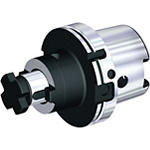
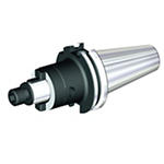
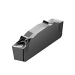
Produkt podobny do:
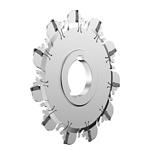
KNS® • Arbor Mount • Reinforced Body • Metric
Slot milling cutter for multiple materials.
Nr materiału5614822
Nr katalogowy ISOKNSM100N11X12K027Nr katalogowy ANSIKNSM100N11X12K027
- P Steel
- M Stainless Steel
- K Cast Iron
- N Non-Ferrous
- S High-Temp Alloys
100055043
Slotting: Side
Sending to {{cadTool}} in progress...
Downloaded file will be available after import in the {{cadTool}} tool library.
- Podsumowanie
- Parametry skrawania
- Do pobrania
- Pasujace produkty - strona maszyny
- Pasujace produkty - strona przedmiotu obrabianego
- Części zamienne
- Opinia
- Q&A
| Nr materiału | 5614822 |
| Nr katalogowy ISO | KNSM100N11X12K027 |
| Nr katalogowy ANSI | KNSM100N11X12K027 |
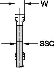
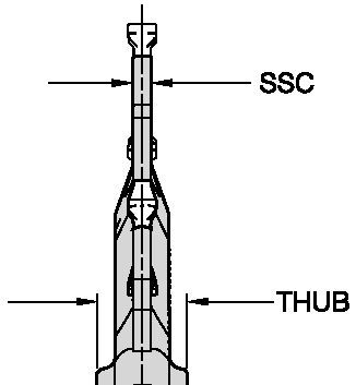
| Insert Size [SSC] | 12 |
| [BM] Cutting Width Minimum | 1.4 mm |
| [BM] Cutting Width Minimum | .055 in |
| [BMAX] Cutting Width Maximum | 1.9 mm |
| [BMAX] Cutting Width Maximum | .075 in |
| [D1] Effective Cutting Diameter | 100 mm |
| [D1] Effective Cutting Diameter | 3.937 in |
| [D] Adapter / Shank / Bore Diameter | 27 mm |
| [D] Adapter / Shank / Bore Diameter | 1.06 in |
| [D6] Hub Diameter | 41 mm |
| [D6] Hub Diameter | 1.61 in |
| [CDX] Radial Maximum Depth of Cut | 9.54 mm |
| [CDX] Radial Maximum Depth of Cut | .375 in |
| [L1S] Secondary Gage Length | 3 mm |
| [L1S] Secondary Gage Length | .118 in |
| [W1] Blade Width | 1.2 mm |
| [W1] Blade Width | .047 in |
| [THUB] Hub Thickness | 6 mm |
| [THUB] Hub Thickness | .236 in |
| Number of Inserts | 11 |
| Gage Insert | XCP12_____ |
| Weight Kilograms | 0.15 |
| Max RPM | 800 |
Materiały przedmiotu obrabianego
- Steel
- Stainless Steel
- Cast Iron
- Non-Ferrous
- High-Temp Alloys
Zastosowania
100055043
Slotting: Side
Właściwości i zalety
- The Double-V Design of the insert and the insert pocket securely holds the insert in place, minimises radial runout, providing high slot width accuracy and high repeatability.
- A unique self-clamping mechanism ensures easy insert exchange.
- Integral hub for high accuracy and repeatability.
- Two-keyway hub design for gang slotting applications.
Złóż nowe rozwiązanie aby obliczyc parametry posuwu i prędkości
Po złóżeniu rozwiązania wybierz ikonę "Posuwy i prędkości" a system pokaże rekomendowane wartości. Możesz doprecyzować wyniki dodając maszynę i jej specyfikacje lub zmień wartości początkowe Używając suwaki.
Dobór płytek
Poradnik doboru płytek
| KNS® Slotting Cutter • Insert Selection Guide | ||||||
| Material Group | Light | General | Heavy | |||
| – | (Light geometry) | (Strong geometry) | ||||
| – | wear |  | toughness | |||
| – | Geometry | Grade | Geometry | Grade | Geometry | Grade |
| P1-P2 | .S..GP | KCU25 | .S..GP | KCU25 | .S..GP | KCPM40 |
| P3-P4 | .S..GP | KCU25 | .S..GP | KCU25 | .S..GP | KCPM40 |
| P5-P6 | .S..GP | KCU25 | .S..GP | KCU25 | .S..GP | KCPM40 |
| M1-M2 | .S..GP | KCU25 | .S..GP | KCPM40 | .S..GP | KCPM40 |
| M3 | .S..GP | KCU25 | .S..GP | KCPM40 | .S..GP | KCPM40 |
| K1-K2 | .S..GP | KCU25 | .S..GP | KCPK30 | .S..GP | KCPK30 |
| K3 | .S..GP | KCU25 | .S..GP | KCPK30 | .S..GP | KCPK30 |
| N1-N2 | – | – | .S..GP | KCU25 | – | – |
| N3 | – | – | .S..GP | KCU25 | – | – |
| S1-S2 | .S..GP | KCU25 | .S..GP | KCU25 | .S..GP | KCU25 |
| S3 | .S..GP | KCU25 | .S..GP | KCU25 | .S..GP | KCU25 |
| S4 | .S..GP | KCU25 | .S..GP | KCU25 | .S..GP | KCU25 |
| H1 | – | – | – | – | – | – |
Posuwy
Zalecane wyjściowe wartości posuwu [mm]
| KNS® Slotting Cutter • Recommended Starting Feeds [mm/th] | ||||||||||||
| Insert Geometry | Recommended Starting Feed per Tooth (Fz) in Relation to % of Radial Engagement (ae) | |||||||||||
| 5% | 10% | 20% | 30–100% | |||||||||
| L | M | H | L | M | H | L | M | H | L | M | H | |
| .S..GP | 0,13 | 0,28 | 0,35 | 0,09 | 0,20 | 0,32 | 0,07 | 0,15 | 0,32 | 0,06 | 0,12 | 0,30 |
| L = Light Machining; M = Medium Machining; H = Heavy Machining NOTE: Use "Light Machining" values as starting feed rate. | ||||||||||||
| KNS® Slotting Cutter • Recommended Starting Feeds [IPT] | ||||||||||||
| Insert Geometry | Recommended Starting Feed per Tooth (Fz) in Relation to % of Radial Engagement (ae) | |||||||||||
| 5% | 10% | 20% | 30–100% | |||||||||
| L | M | H | L | M | H | L | M | H | L | M | H | |
| .S..GP | 0.005 | 0.011 | 0.027 | 0.004 | 0.008 | 0.020 | 0.003 | 0.006 | 0.015 | 0.002 | 0.005 | 0.012 |
| L = Light Machining; M = Medium Machining; H = Heavy Machining NOTE: Use "Light Machining" values as starting feed rate. | ||||||||||||
Prędkości
Zalecane wyjściowe wartości prędkości skrawania [m/min]
| KNS® Slotting Cutter • Recommended Starting Speed [m/min] | ||||||||||
| Grade | KCU25 | KCPK30 | KMF | |||||||
| Chip Thickness hex mm | Min | Max | Min | Max | Min | Max | ||||
| Material Group | Max | Start | Min | Max | Start | Min | Max | Start | Min | |
| P | 1 | 260 | 230 | 215 | 455 | 395 | 370 | 295 | 260 | 245 |
| 2 | 220 | 190 | 160 | 280 | 255 | 230 | 250 | 215 | 180 | |
| 3 | 200 | 170 | 140 | 255 | 230 | 205 | 230 | 195 | 160 | |
| 4 | 180 | 150 | 120 | 225 | 185 | 160 | 205 | 170 | 135 | |
| 5 | 150 | 135 | 120 | 190 | 170 | 150 | 170 | 155 | 135 | |
| 6 | 130 | 100 | 80 | 160 | 135 | 110 | 150 | 115 | 90 | |
| M | 1 | 210 | 170 | 135 | 205 | 185 | 155 | 195 | 170 | 155 |
| 2 | 170 | 150 | 110 | 185 | 160 | 140 | 175 | 150 | 125 | |
| 3 | 130 | 120 | 85 | 145 | 130 | 115 | 130 | 115 | 90 | |
| K | 1 | 270 | 220 | 170 | 295 | 265 | 240 | – | – | – |
| 2 | 230 | 190 | 160 | 235 | 210 | 190 | – | – | – | |
| 3 | 210 | 160 | 140 | 195 | 175 | 160 | – | – | – | |
| N | 1 | – | – | – | – | – | – | – | – | – |
| 2 | – | – | – | – | – | – | – | – | – | |
| 3 | – | – | – | – | – | – | – | – | – | |
| S | 1 | 30 | 25 | 20 | – | – | – | 40 | 35 | 30 |
| 2 | 30 | 25 | 20 | – | – | – | 40 | 35 | 30 | |
| 3 | 40 | 30 | 20 | – | – | – | 50 | 40 | 30 | |
| 4 | 55 | 40 | 25 | 50 | 45 | 35 | 55 | 50 | 35 | |
| H | 1 | – | – | – | – | – | – | – | – | – |
| Recommended Starting Speed are pointing to 90° Shoulder Milling . Starting Speed for Face and Copy Milling can be Increased by 20 %. As the average chip thickness increases, speed should be decreased. Material groups P, M, K and H show recommended starting speeds for dry machining. For wet machining, reduce speed by 20%. Material groups N and S show recommended starting speeds for wet machining. Not recommended for dry machining. | ||||||||||
| KNS® Slotting Cutter • Recommended Starting Speed [SFM] | ||||||||||
| Grade | KCPK30 | KCPK30 | KMF | |||||||
| Chip Thickness hex Inch | Min | Max | Min | Max | Min | Max | ||||
| Material Group | Max | Start | Min | Max | Start | Min | Max | Start | Min | |
| P | 1 | 855 | 755 | 705 | 1495 | 1295 | 1215 | 970 | 855 | 805 |
| 2 | 720 | 625 | 525 | 920 | 835 | 755 | 820 | 705 | 590 | |
| 3 | 655 | 560 | 460 | 835 | 755 | 675 | 755 | 640 | 525 | |
| 4 | 590 | 490 | 395 | 740 | 605 | 525 | 675 | 560 | 445 | |
| 5 | 490 | 445 | 395 | 625 | 560 | 490 | 560 | 510 | 445 | |
| 6 | 425 | 330 | 260 | 525 | 445 | 360 | 490 | 375 | 295 | |
| M | 1 | 690 | 560 | 445 | 675 | 605 | 510 | 640 | 560 | 510 |
| 2 | 560 | 490 | 360 | 605 | 525 | 460 | 575 | 490 | 410 | |
| 3 | 425 | 395 | 280 | 475 | 425 | 375 | 425 | 375 | 295 | |
| K | 1 | 885 | 720 | 560 | 970 | 870 | 785 | – | – | – |
| 2 | 755 | 625 | 525 | 770 | 690 | 625 | – | – | – | |
| 3 | 690 | 525 | 460 | 640 | 575 | 525 | – | – | – | |
| N | 1 | – | – | – | – | – | – | – | – | – |
| 2 | – | – | – | – | – | – | – | – | – | |
| 3 | – | – | – | – | – | – | – | – | – | |
| S | 1 | 100 | 80 | 65 | – | – | – | 130 | 115 | 100 |
| 2 | 100 | 80 | 65 | – | – | – | 130 | 115 | 100 | |
| 3 | 130 | 100 | 65 | – | – | – | 165 | 130 | 100 | |
| 4 | 180 | 130 | 80 | 165 | 150 | 115 | 180 | 165 | 115 | |
| H | 1 | – | – | – | – | – | – | – | – | – |
| Recommended Starting Speed are pointing to 90° Shoulder Milling . Starting Speed for Face and Copy Milling can be Increased by 20 %. As the average chip thickness increases, speed should be decreased. Material groups P, M, K and H show recommended starting speeds for dry machining. For wet machining, reduce speed by 20%. Material groups N and S show recommended starting speeds for wet machining. Not recommended for dry machining. | ||||||||||
CAD Drawings Models
Can’t find the file type you’re looking for?
Product data
I have read and accepted the Terms & Conditions of use
