Machinist's Guide: Face Milling vs. Peripheral Milling – What's the Difference?

October 7, 2022

by Kennametal Metal Cutting Pros

Successful milling operations require that the machinist remove material both quickly and accurately. Achieving this depends on several factors, including the quality of the cutting tool, what feed rates and cutting speeds are used, and which toolpaths are most effective. It’s this last point in particular that seems to have some people confused, especially given the increased use of modern metal removal strategies such as trochoidal milling and other high-efficiency milling methods.

What is Face Milling?

One of the first and most fundamental operations that must be performed on any machined part is face milling. As its name describes, the face milling process makes the top of a workpiece—the surface positioned closest to the machine spindle—both flat and smooth. It also establishes what’s known in CNC programming parlance as Z0, the “datum” from which hole and pocket depths are measured.

How Does the Face Mill Work?

As with drills and other cutting tools, a face mill requires several conditions to work efficiently. The first is that the machine spindle holding the cutting tool must rotate at the appropriate RPM. This “rotational velocity” is determined by a basic formula that considers the material's cutting speed together with the diameter of the cutting tool. Regardless, once the spindle has begun turning, the face mill can then be “fed” across the top of the workpiece, using the end of the cutting tool to remove material as it goes.

This feedrate is in turn determined by the number of teeth on the cutter, the type of material, the “depth of cut” in the vertical direction (the Z-axis), the rigidity of the machine tool, and the amount of workholding force applied by the vise or fixture. Heavier cuts and harder, tougher metals such as superalloys and stainless steel require greater power, smaller depths of cut, or lighter feedrates, and sometimes all three. Soft materials like aluminum and mild steel are just the opposite. Either way, multiple "roughing" passes might be required to bring the workpiece to the required dimensions, as well as a “finishing” pass for cleanup.

Due to its positive lead angle, face mills like the KSSM 45º shown here cannot be used to machine a square shoulder.


What is Peripheral Milling?

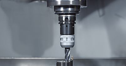
Face milling’s counterpart is peripheral milling. Ironically, it uses an end mill or sometimes a shell mill, even though most of the material removal occurs on the cutting tool's sides, or flutes. If you’ve never seen one, an end mill looks a lot like a drill bit. Both have helical flutes (usually), except that an end mill is flat at the end rather than pointed like a drill. Also, drills typically have only two flutes, whereas end mills often have four or more. 

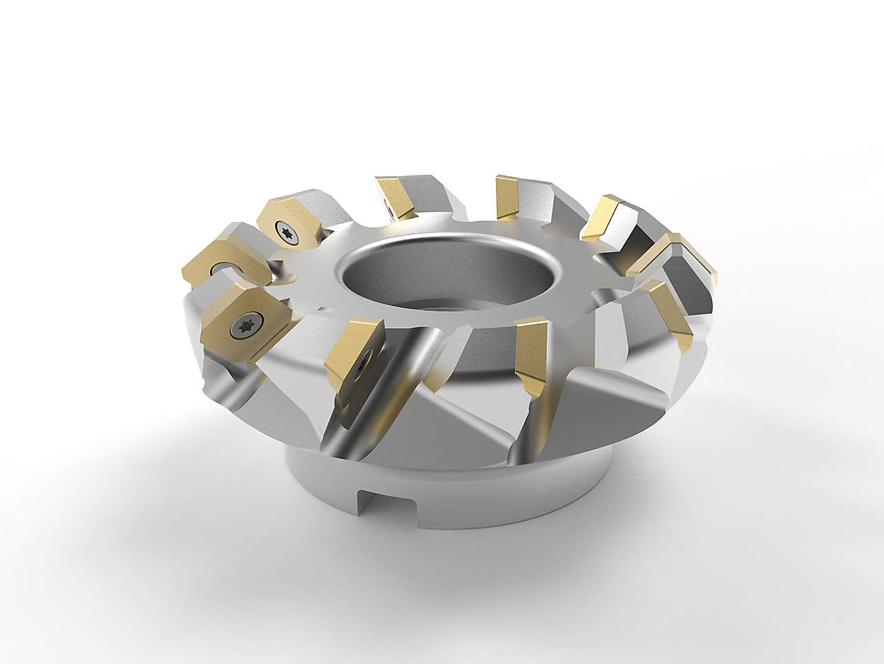
Where a face mill removes material from the workpiece’s top surface, an end mill (and its larger cousin, the shell mill) removes it from the part’s periphery, as well as from the inside of a pocket (or pockets) within the part. Depending on the milling strategy, the tool is positioned to a predetermined depth (again, in the Z-axis) and then fed into and around the workpiece until complete. As with face milling, success with peripheral milling depends on the right feedrates and cutting speeds, appropriate depths of cut, and adequate machine power and clamping force.

It should also be noted that an end mill can be used to perform face milling, albeit not as efficiently as a face mill. For example, the bottom of the pocket just mentioned must be machined flat, and since face mills are generally too large to fit inside a workpiece, an end mill is the only option. Also, most face mills (though not all) cannot machine a square shoulder, so once more, an end mill or shell mill must be used. 

Finally, ball-nosed and radiused end mills are typically used to machine the inside surfaces of mold cavities and other three-dimensional shapes. A face mill, by contrast, can only machine flat surfaces perpendicular to the axis of the machine spindle. More than any other factor, this perpendicularity defines the difference between peripheral milling and face milling—where the latter is always at a right angle to the spindle, peripheral milling or end milling is always done in a parallel direction. 


Though end mills are also available with indexable inserts, solid carbide tools like this HARVI™ I four-flute, center cutting end mills are the preferred tool for finishing operations and high-performance roughing. 

Tips for Milling Operations

As mentioned, successful milling of all kinds depends on the correct cutting parameters. Most machining experts—Kennametal’s included—will tell you that machinists are often too conservative in this respect, using cutting speeds and feedrates lower than the cutting tool manufacturer’s recommendations. The message is clear: always partner with a reputable supplier and follow their advice. 

Once you've determined the correct feeds, speeds, and depths of cut for the material and workholding conditions, it's time to look at the toolholding. End mills, face mills, drills, and all other milling cutters are rotary tools. As such, they must be gripped in a manner that eliminates runout. This means that the axis of the cutting tool is perfectly aligned with that of the toolholder. If not, the tool tends to cut on one side more than the other, leading to poor tool life and part surface finish. 

The entire toolholder assembly, meaning the cutting tool, the chuck or collet holder, and the retention knob that secures the toolholder within the machine spindle, should also be balanced. If your ceiling fan wobbles or the tires on your car shake, they're out of balance. Again, failure to address this problem, especially at higher spindle speeds (say 8,000 RPM and above), reduces tool life and part quality. 

Finally, make certain the cutting tool cannot move within the toolholder. Face mills are usually attached to an arbor, eliminating movement, but machinists often used so-called sidelock and Weldon-flat toolholders to grip end mills and larger drills. These old-fashioned toolholders are notorious for "tool creep" during heavy machining operations. They also induce runout and out-of-balance conditions. Better alternatives include modern hydraulic or mechanical milling chucks and shrink-fit toolholders. As always, feel free to reach out to Kennametal or your area’s tooling representative for advice on these and other machining topics. 

Harvi Ultra 8X

This HARVI™ Ultra 8X image illustrates a shell mill’s similarity to a helical end mill, as well as the use of an arbor mount for maximum security and minimal runout. 

Related Articles

You are about to add to your My Solutions page. Do you want to proceed?
product-image
Please adjust the following properties from

ISO Catalog Number

ANSI Catalog Number

to find similar products.

The following files are available

Please select a file to download

Models

You should be logged to see your dashboard information
Session expired due to inactivity, please login again
The product/s () you were trying to add to the cart is/are not available, please contact customer service
item(s) successfully added to the cart
View Cart

. Please enter the desired qty for the material(s) you want to include in your promotion or Proceed Without Promotion and only your base materials will be added to the cart.

Minimum quantity should be

SAP Material Number ISO Catalog Number Grade    

Thank you for your registration, pending approval & completion of the registration, your access is currently limited. Full utilization of product search capabilities & collaboration space is available and will remain. Please allow 2 business days for registration completion.

Thank you for your successful registration. You now have immediate access to log in and utilize the site.

You are about to leave the Solution building process.

Are you sure you want to leave?