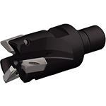
Back to Solution
Editing Solution
Adding Solution
Solution Name: {{SolutionName}}
Filters and Columns
Filters
Filters
Filters
View filters in
Metric
Inch
Workpiece Material
Workpiece Material
-
K Cast Iron (3)
-
K1Gray Cast Iron 120-290 HB; <32 HRC; 125-500 N/mm^2 UTS(3)
-
K2Low and Medium Strength CGI and Ductile Irons 130-260 HB; <28 HRC; <600 N/mm^2 UTS(3)
-
K3High Strength Ductile and Austempered Ductile Iron 180-350 HB; <43 HRC; >600 N/mm^2 UTS(3)
-
-
N Non-Ferrous Materials (3)
-
N1Wrought Aluminum(3)
-
N2Low-Silicon Aluminum Alloys and Magnesium Alloys Si <12.2%(3)
-
N3High-Silicon Aluminum Alloys Si >12.2%(3)
-
Applications
Applications
-
Face Milling (3)
-
Pocket Milling (3)
-
Profile Milling (3)
-
Ramping (3)
-
Shoulder Bottom Shoulder (3)
-
Shoulder Milling (3)
-
Shoulder Roughing (3)
-
Shoulder Square End (3)
-
Slot Milling (3)
-
Slot Side (3)
-
Slot Square End (3)
-
Slot T (3)
Cutting Diameter
Cutting Diameter
-
1.0 in (1)
-
1.25 in (2)
to
Cutting Diameter
Cutting Diameter
-
25.401 mm (1)
-
31.75 mm (2)
to
Reach
Reach
-
1.967 in (1)
-
1.969 in (2)
to
Reach
Reach
-
49.95 mm (1)
-
50.0 mm (2)
to
Number of Flutes
Number of Flutes
-
2 (2)
-
3 (1)
Corner Radius
Corner Radius
-
0.012 in (3)
-
0.016 in (3)
-
0.031 in (3)
-
0.049 in (3)
-
0.066 in (3)
-
0.083 in (3)
-
0.103 in (3)
-
0.122 in (3)
-
0.13 in (3)
-
0.161 in (3)
-
0.206 in (3)
-
0.244 in (3)
to
Corner Radius
Corner Radius
-
0.301 mm (3)
-
0.4 mm (3)
-
0.8 mm (3)
-
1.25 mm (3)
-
1.675 mm (3)
-
2.1 mm (3)
-
2.6 mm (3)
-
3.1 mm (3)
-
3.301 mm (3)
-
4.101 mm (3)
-
5.2 mm (3)
-
6.2 mm (3)
to
Application
Maximum Ramp Angle
Maximum Ramp Angle
-
11.5 (2)
-
14.7 (1)
to
Back-End
Back-End Diameter
Back-End Diameter
-
21.0 mm (1)
-
29.0 mm (2)
to
Back-End Diameter
Back-End Diameter
-
0.828 in (1)
-
1.143 in (2)
to
No filters matching ""
Change the visible columns with any of the parameters listed below. A maximum of 7 columns can be displayed.
Displaying
1- 3
of 3 results
Metric
Inch
Show
Metric
Inch
SAP Material Number | ISO Catalog Number | ANSI Catalog Number | [D1] Effective Cutting Diameter | [D1] Effective Cutting Diameter | [D] Adapter / Shank / Bore Diameter | [D] Adapter / Shank / Bore Diameter | [DPM] Pilot Diameter Machine Side | [DPM] Pilot Diameter Machine Side | [G3X] Connection Thread Size External | [L2] Head Length | [L2] Head Length | [WF] Width of Flat | [WF] Width of Flat | ||||||||||||||||||||||||||||||||||||||||||||||||||||||||||||||||||||||||||||||||||||||
---|---|---|---|---|---|---|---|---|---|---|---|---|---|---|---|---|---|---|---|---|---|---|---|---|---|---|---|---|---|---|---|---|---|---|---|---|---|---|---|---|---|---|---|---|---|---|---|---|---|---|---|---|---|---|---|---|---|---|---|---|---|---|---|---|---|---|---|---|---|---|---|---|---|---|---|---|---|---|---|---|---|---|---|---|---|---|---|---|---|---|---|---|---|---|---|---|---|---|---|
5672512 | A5720VZ16SA1.00Z2R2 | A5720VZ16SA1.00Z2R2 | 25.4000 | 1.000 | 21.0 | .8268 | 12.5000 | .4921 | M12 | 50.0000 | 1.968 | 18.0000 | .7087 |
|
|||||||||||||||||||||||||||||||||||||||||||||||||||||||||||||||||||||||||||||||||||||
List price:
$416.12
/each
Your price:
Qty
|
|||||||||||||||||||||||||||||||||||||||||||||||||||||||||||||||||||||||||||||||||||||||||||||||||||
5672719 | A5720VZ16SA1.25Z2R2 | A5720VZ16SA1.25Z02R2 | 31.7500 | 1.250 | 29.0 | 1.141 | 17.0000 | .6693 | M16 | 50.0000 | 1.968 | 24.0000 | .9449 |
|
|||||||||||||||||||||||||||||||||||||||||||||||||||||||||||||||||||||||||||||||||||||
List price:
$416.12
/each
Your price:
Qty
|
|||||||||||||||||||||||||||||||||||||||||||||||||||||||||||||||||||||||||||||||||||||||||||||||||||
5672521 | A5720VZ16SA1.25Z3R2 | A5720VZ16SA1.25Z3R2 | 31.7500 | 1.250 | 29.0 | 1.141 | 17.0000 | .6693 | M16 | 49.9500 | 1.966 | 24.0000 | .9449 |
|
|||||||||||||||||||||||||||||||||||||||||||||||||||||||||||||||||||||||||||||||||||||
List price:
$516.73
/each
Your price:
Qty
|
List price:
Discount: %
Replacement
This item is no longer available
Replacement Product Please contact customer service for assistance
Qty
Sold in pkg. of
Insert Selection Guide
Material Group | Light Machining | General Purpose | Heavy Machining | |||
– | (Light geometry) | (Strong geometry) | ||||
– | wear resistance | toughness | ||||
– | Geometry | Grade | Geometry | Grade | Geometry | Grade |
P1–P2 | – | – | – | – | – | – |
P3–P4 | – | – | – | – | – | – |
P5–P6 | – | – | – | – | – | – |
M1–M2 | – | – | – | – | – | – |
M3 | – | – | – | – | – | – |
K1–K2 | – | – | – | – | – | – |
K3 | – | – | – | – | – | – |
N1–N2 | .F..721 | GH1 | .F..721 | GH1 | .F..721 | GH1 |
N3 | .F..721 | GH1 | .F..721 | GH1 | .F..721 | GH1 |
S1–S2 | – | – | – | – | – | – |
S3 | – | – | – | – | – | – |
S4 | – | – | – | – | – | – |
H1 | – | – | – | – | – | – |
Recommended Starting Feeds [mm]
Insert Geometry | Programmed Feed per Tooth (fz) at % Radial Depth of Cut (ae) of Working Diameter (Dw) | Insert Geometry | ||||||||||||
5% | 10% | 20% | 40–100% | |||||||||||
...FR721 | 0,03 | 0,33 | 0,41 | 0,025 | 0,25 | 0,31 | 0,021 | 0,21 | 0,27 | 0,02 | 0,20 | 0,25 | ...FR721 | |
...ER721 | 0,07 | 0,33 | 0,41 | 0,06 | 0,25 | 0,31 | 0,05 | 0,21 | 0,27 | 0,04 | 0,20 | 0,25 | ...ER721 |
5720VZ16 Feeds fz (mm/tooth)
Light Machining | General Purpose | Heavy Machining |
size | Geometry | grade | operation | N | |
Aluminium and Alloys 16% Si 116 HBN | Aluminium and Silicon 16% Si 92 HBN | ||||
min–max | min–max | ||||
14mm | ...721 | GH1 | Profiling/Pocketing | 0,02 0,25 | 0,02 0,20 |
Recommended Starting Feeds [IPT]
Light Machining | General Purpose | Heavy Machining |
Insert Geometry | Recommended Starting Feed per Tooth (Fz) in Relation to % of Radial Engagement (ae) | Insert Geometry | |||||||||||
10% | 20% | 30% | 40–100% | ||||||||||
.F..721 | .001 | .013 | .016 | .001 | .010 | .012 | .001 | .008 | .011 | .001 | .008 | .010 | .F..721 |
.E..721 | .003 | .013 | .016 | .002 | .010 | .012 | .002 | .008 | .011 | .002 | .008 | .010 | .E..721 |