Scheduled Site Maintenance
Kennametal.com may be briefly unavailable for scheduled maintenance starting September 22nd at 8:30 PM EST through September 24th at 8:30 AM EST.
Read More


Micron by Micron - Precision Adjustment is as Easy as 1, 2, 3

The eBore boring system covers a diameter range from 6-1020mm by providing state-of-the-art fine boring tooling solutions that have one thing in common: all of them are digital ready.

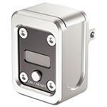
The digital eBore display provides the option to readjust the tool on the spindle, reducing setup time and idle time.

One for all - One eBore digital display serving all eBore fine boring tools.

Micron by micron, the precision adjustment of each tool is just as easy as 1, 2, 3.


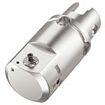
eBore Universal

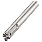
eBore Fine Boring

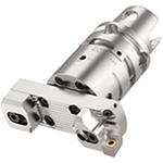
eBore Bridge Tools

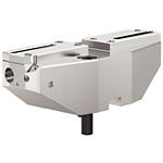
eBore Twin Cutter


eBore Digital Display

eBore™  Manuals

View Now

eBore™ Features

  • Dial for manual adjustment.
  • Upgrade from analog to digital possible.
  • Versatility through various fine boring tooling options.
  • Diameter range from 6-1020mm.
  • Precision fine boring with ease.
  • Adjustment of each tool micron by micron.
  • Tool re-adjustment on the spindle.


Application Information


Browse eBore™ Products

Select Filters
Filters
View filters in
Metric
Inch
Key Filters
Workpiece Material
Workpiece Material
  • P Steel (44)
    • P0
      Low-Carbon Steels, Long Chipping C < .25%; <125 HB; <530 N/mm^2 UTS (44)
    • P1
      Low-Carbon Steels, Short Chipping C < .25%; <125 HB; <530 N/mm^2 UTS (44)
    • P2
      Medium and High Carbon Steels C < .25%; <220 HB; <25 HRC; >530 N/mm^2 UTS (44)
    • P3
      Alloy Steels & Tool Steels C > .25%; <330 HB; <35 HRC; 600-850 N/mm^2 UTS (44)
    • P4
      Alloy Steels & Tool Steels C > .25%; 350-420 HB; 35-43 HRC; 850-1400 N/mm^2 UTS (44)
    • P5
      Ferritic, Martensitic, and PH Stainless Steels <330 HB; <35 HRC; 600-900 N/mm^2 UTS (44)
    • P6
      High Strength Ferritic, Martensitic, and PH Stainless Steels 350-450 HB; 35-43 HRC; 900-2400 N/mm^2 UTS (44)
  • M Stainless Steel (44)
    • M1
      Austenitic Stainless Steel 130-200 HB; <600 N/mm^2 UTS (44)
    • M2
      High Strength Austenitic Stainless and Cast Stainless Steels 150-230 HB; <25 HRC; >600 N/mm^2 UTS (44)
    • M3
      Duplex Stainless Steel 135-275 HB; <30 HRC; 500-1200 N/mm^2 UTS (44)
  • K Cast Iron (39)
    • K1
      Gray Cast Iron 120-290 HB; <32 HRC; 125-500 N/mm^2 UTS (39)
    • K2
      Low and Medium Strength CGI and Ductile Irons 130-260 HB; <28 HRC; <600 N/mm^2 UTS (39)
    • K3
      High Strength Ductile and Austempered Ductile Iron 180-350 HB; <43 HRC; >600 N/mm^2 UTS (39)
  • N Non-Ferrous Materials (39)
    • N1
      Wrought Aluminum (39)
    • N2
      Low-Silicon Aluminum Alloys and Magnesium Alloys Si <12.2% (39)
    • N3
      High-Silicon Aluminum Alloys Si >12.2% (39)
    • N4
      Copper, Brass, Zinc-based on machinability index range of 70-100 (39)
    • N5
      Nylon, Plastics, Rubbers, Phenolics, Resins, Fiberglass (39)
    • N6
      Carbon, Graphite Composites, CFRP (39)
    • N7
      MMC's (39)
  • S High-Temp Alloys (44)
    • S1
      Iron-Based, Heat-Resistant Alloys 160-260 HB; 25-48 HRC; 500-1200 N/mm^2 UTS (44)
    • S2
      Cobalt-Based, Heat-Resistant Alloys 250-450 HB; 25-48 HRC; 1000-1450 N/mm^2 UTS (44)
    • S3
      Nickel-Based, Heat Resistant Alloys 160-450 HB; <48 HRC; 600-1700 N/mm^2 UTS (44)
    • S4
      Titanium and Titanium Alloys 300-400 HB; 33-43 HRC; 900-1600 N/mm^2 UTS (44)
  • H Hardened Materials (39)
    • H1
      Hardened Materials 44-48 HRC (39)
    • H2
      Hardened Materials 48-55 HRC (39)
    • H3
      Hardened Materials 56-60 HRC (39)
    • H4
      Hardened Materials >60 HRC (39)
Applications
Applications
  • Blind & Cross Hole Finishing Blind & Cross Hole Finishing (71)
  • Blind Hole Finishing Blind Hole Finishing (71)
  • Through & Cross Hole Finishing Through & Cross Hole Finishing (71)
  • Through Hole Finishing Through Hole Finishing (71)
Cutting Condition
Cutting Condition
  • Heavily Interrupted Cut (39)
  • Lightly Interrupted Cut (44)
  • Smooth Cut (44)
  • Varying Depth of Cut (44)
Tool Cutting Edge Angle
  • 90.0 (12)
  • 91.0 (8)
  • 92.0 (23)
Tool Cutting Edge Angle Min to Tool Cutting Edge Angle Max
Connection Style
Connection Style
  • E-BORE Boring Bar (21)
Cutting Edges Per Insert
  • 1.0 (17)
  • 2.0 (17)
  • 3.0 (5)
  • 4.0 (17)
Cutting Edges Per Insert Min to Cutting Edges Per Insert Max
Internal Coolant Capability
Over All Length [L]
Over All Length [L]
  • 0.36 in (1)
  • 0.395 in (1)
  • 0.496 in (3)
  • 0.574 in (1)
  • 0.576 in (1)
  • 0.592 in (1)
  • 0.65 in (2)
  • 0.669 in (3)
  • 0.811 in (1)
  • 0.816 in (2)
  • 1.0 in (1)
  • 1.205 in (1)
  • 1.209 in (3)
  • 1.772 in (1)
  • 1.891 in (1)
  • 2.086 in (1)
  • 2.087 in (1)
  • 2.165 in (1)
  • 2.265 in (1)
  • 2.282 in (2)
  • 2.479 in (1)
  • 2.676 in (1)
  • 2.677 in (1)
  • 2.873 in (1)
  • 3.071 in (1)
  • 3.269 in (1)
  • 3.661 in (2)
  • 3.858 in (2)
  • 4.449 in (2)
  • 4.843 in (1)
  • 5.63 in (1)
Over All Length [L] Min to Over All Length [L] Max
Over All Length [L]
Over All Length [L]
  • 9.15 mm (1)
  • 10.025 mm (1)
  • 12.601 mm (3)
  • 14.55 mm (1)
  • 14.601 mm (1)
  • 15.025 mm (1)
  • 16.5 mm (2)
  • 17.0 mm (3)
  • 20.6 mm (1)
  • 20.701 mm (2)
  • 25.401 mm (1)
  • 30.6 mm (1)
  • 30.701 mm (3)
  • 45.0 mm (1)
  • 48.0 mm (1)
  • 52.975 mm (1)
  • 53.0 mm (1)
  • 55.0 mm (1)
  • 57.5 mm (1)
  • 57.975 mm (2)
  • 62.975 mm (1)
  • 67.976 mm (1)
  • 68.0 mm (1)
  • 72.976 mm (1)
  • 78.0 mm (1)
  • 83.0 mm (1)
  • 93.0 mm (2)
  • 98.0 mm (2)
  • 113.0 mm (2)
  • 123.0 mm (1)
  • 143.0 mm (1)
Over All Length [L] Min to Over All Length [L] Max
Corner configuration
Corner Radius
Corner Radius
  • 0.002 in (32)
  • 0.004 in (44)
  • 0.008 in (39)
  • 0.016 in (39)
  • 0.031 in (39)
  • 0.047 in (10)
  • 0.063 in (3)
Corner Radius Min to Corner Radius Max
Corner Radius
Corner Radius
  • 0.05 mm (32)
  • 0.1 mm (44)
  • 0.2 mm (39)
  • 0.4 mm (39)
  • 0.8 mm (39)
  • 1.201 mm (10)
  • 1.6 mm (3)
Corner Radius Min to Corner Radius Max
Corner Chamfer
Corner Chamfer
  • 0.0 mm (23)
Corner Chamfer Min to Corner Chamfer Max
Corner Chamfer
Corner Chamfer
  • 0.0 in (23)
Corner Chamfer Min to Corner Chamfer Max
Application
Minimum Depth of Cut
Minimum Feed
Minimum Feed
Grade Of Cutting Tool
  • HCK10 (39)
  • HK1500 (32)
  • HK35 (36)
  • HT2 (39)
  • HTX (39)
  • HWK15 (39)
  • K10M (36)
  • K10P (36)
  • K10U (32)
  • K15U (32)
  • K20K (36)
  • K25M (29)
  • K313 (39)
  • K68 (39)
  • KB1345 (10)
  • KB1610 (32)
  • KB1630 (39)
  • KB5610 (32)
  • KB5625 (32)
  • KB5630 (32)
  • KB9610 (32)
  • KBH10 (32)
  • KBH20 (39)
  • KC5010 (39)
  • KC5025 (39)
  • KC5410 (39)
  • KC720 (39)
  • KC730 (39)
  • KC732 (39)
  • KC8050 (39)
  • KC810 (39)
  • KC850 (39)
  • KC9010 (32)
  • KC9025 (39)
  • KC910 (39)
  • KC9105 (39)
  • KC9110 (39)
  • KC9120 (32)
  • KC9125 (39)
  • KC9225 (39)
  • KC9240 (39)
  • KC9240NEW (39)
  • KC9315 (39)
  • KC9320 (39)
  • KC9325 (39)
  • KC935 (39)
  • KC950 (32)
  • KC990 (32)
  • KCD25 (39)
  • KCK05 (39)
  • KCK05B (32)
  • KCK15 (39)
  • KCK15B (39)
  • KCK20 (39)
  • KCK20B (39)
  • KCM15 (39)
  • KCM15B (39)
  • KCM25 (39)
  • KCM25B (39)
  • KCM35 (39)
  • KCM35B (3)
  • KCP05 (39)
  • KCP05B (3)
  • KCP10 (39)
  • KCP10B (39)
  • KCP25 (39)
  • KCP25B (39)
  • KCP25C (39)
  • KCP30 (39)
  • KCP30B (10)
  • KCS10 (39)
  • KCS10B (39)
  • KCU10 (44)
  • KCU10B (39)
  • KCU25 (39)
  • KD050 (32)
  • KD081 (32)
  • KD1400 (32)
  • KD1425 (32)
  • KT175 (32)
  • KT315 (39)
  • KT325 (39)
  • KTP10 (32)
  • KU10 (32)
  • KU10T (39)
  • KU30T (39)
  • NL300 (7)
  • NL920 (7)
  • PB100 (29)
  • PB170 (36)
  • PB250 (36)
  • PB300 (29)
  • PD100 (39)
  • PD50 (36)
  • SP0PW3 (7)
  • SP4019 (7)
  • SPN3W1 (3)
  • THM (39)
  • THM-X (39)
  • TN1000 (29)
  • TN10P (39)
  • TN10U (39)
  • TN15M (39)
  • TN15U (32)
  • TN2000 (39)
  • TN20K (39)
  • TN20P (39)
  • TN30M (39)
  • TN4000 (32)
  • TN5015 (39)
  • TN5020 (39)
  • TN5105 (39)
  • TN5120 (39)
  • TN6010 (10)
  • TN6025 (3)
  • TN7005 (3)
  • TN7010 (39)
  • TN7015 (39)
  • TN7025 (39)
  • TN7035 (39)
  • TN7105 (39)
  • TN7110 (39)
  • TN7115 (39)
  • TN7125 (39)
  • TN7135 (39)
  • TN8025 (39)
  • TTI15 (32)
  • TTM (3)
  • TTR (39)
  • TTS (32)
  • TTX (3)
  • W00342 (7)
  • WBH10C (32)
  • WBH10P (32)
  • WBH10U (32)
  • WBH20P (10)
  • WBH25P (32)
  • WBH30P (3)
  • WBK45U (10)
  • WDN00U (32)
  • WDN25U (32)
  • WK05CT (39)
  • WK15CT (39)
  • WK20CT (39)
  • WM15CT (39)
  • WM25CT (39)
  • WP15CT (39)
  • WP20TT (29)
  • WP25CT (39)
  • WP35CT (10)
  • WS10PT (39)
  • WS25PT (32)
  • WU05PT (39)
  • WU10HT (39)
  • WU10PR (4)
  • WU10PT (39)
  • WU20HT (29)
  • WU25PT (39)
Hand Of Tool
Hand Of Tool
  • R (21)
Wiper Insert
Wiper Insert
  • N (22)
F Dimension
F Dimension
  • 0.151 mm (1)
  • 2.825 mm (2)
  • 3.825 mm (1)
  • 4.75 mm (1)
  • 4.775 mm (3)
  • 5.75 mm (2)
  • 5.775 mm (1)
  • 6.75 mm (2)
  • 6.775 mm (2)
  • 7.325 mm (1)
  • 7.75 mm (1)
  • 7.775 mm (2)
  • 9.775 mm (1)
  • 12.275 mm (1)
F Dimension Min to F Dimension Max
F Dimension
F Dimension
  • 0.006 in (1)
  • 0.111 in (2)
  • 0.151 in (1)
  • 0.187 in (1)
  • 0.188 in (3)
  • 0.226 in (2)
  • 0.227 in (1)
  • 0.266 in (2)
  • 0.267 in (2)
  • 0.289 in (1)
  • 0.305 in (1)
  • 0.306 in (2)
  • 0.385 in (1)
  • 0.483 in (1)
F Dimension Min to F Dimension Max
Minimum Axial Groove Diameter
  • 2.0 mm (1)
  • 6.0 mm (2)
  • 8.0 mm (2)
  • 10.0 mm (4)
  • 12.0 mm (3)
  • 14.0 mm (4)
  • 15.0 mm (1)
  • 16.0 mm (3)
  • 19.5 mm (1)
  • 20.0 mm (1)
  • 22.5 mm (1)
  • 24.5 mm (1)
  • 25.0 mm (1)
  • 25.5 mm (1)
  • 29.0 mm (2)
  • 36.0 mm (2)
  • 40.0 mm (1)
  • 43.0 mm (1)
  • 52.0 mm (1)
  • 53.0 mm (1)
  • 65.0 mm (2)
  • 68.0 mm (1)
  • 76.0 mm (1)
  • 82.0 mm (1)
  • 100.0 mm (1)
  • 125.0 mm (1)
  • 200.0 mm (2)
Minimum Axial Groove Diameter Min to Minimum Axial Groove Diameter Max
Minimum Axial Groove Diameter
  • 0.079 in (1)
  • 0.237 in (2)
  • 0.315 in (2)
  • 0.394 in (4)
  • 0.473 in (3)
  • 0.551 in (4)
  • 0.591 in (1)
  • 0.63 in (3)
  • 0.768 in (1)
  • 0.787 in (1)
  • 0.886 in (1)
  • 0.965 in (1)
  • 0.984 in (1)
  • 1.004 in (1)
  • 1.143 in (2)
  • 1.417 in (2)
  • 1.575 in (1)
  • 1.693 in (1)
  • 2.047 in (1)
  • 2.087 in (1)
  • 2.559 in (2)
  • 2.677 in (1)
  • 2.992 in (1)
  • 3.228 in (1)
  • 3.938 in (1)
  • 4.921 in (1)
  • 7.875 in (2)
Minimum Axial Groove Diameter Min to Minimum Axial Groove Diameter Max
Maximum Axial Groove Diameter
  • 0.315 in (2)
  • 0.394 in (2)
  • 0.473 in (4)
  • 0.551 in (3)
  • 0.63 in (4)
  • 0.787 in (4)
  • 0.906 in (1)
  • 0.984 in (1)
  • 1.024 in (1)
  • 1.181 in (2)
  • 1.457 in (2)
  • 1.614 in (1)
  • 1.732 in (1)
  • 2.087 in (1)
  • 2.126 in (1)
  • 2.283 in (1)
  • 2.598 in (2)
  • 3.031 in (1)
  • 3.269 in (1)
  • 4.016 in (1)
  • 4.055 in (1)
  • 5.118 in (1)
  • 5.984 in (1)
  • 8.071 in (2)
  • 40.158 in (2)
Maximum Axial Groove Diameter Min to Maximum Axial Groove Diameter Max
Maximum Axial Groove Diameter
  • 8.0 mm (2)
  • 10.0 mm (2)
  • 12.0 mm (4)
  • 14.0 mm (3)
  • 16.0 mm (4)
  • 20.0 mm (4)
  • 23.0 mm (1)
  • 25.0 mm (1)
  • 26.0 mm (1)
  • 30.0 mm (2)
  • 37.0 mm (2)
  • 41.0 mm (1)
  • 44.0 mm (1)
  • 53.0 mm (1)
  • 54.0 mm (1)
  • 58.0 mm (1)
  • 66.0 mm (2)
  • 77.0 mm (1)
  • 83.0 mm (1)
  • 102.0 mm (1)
  • 103.0 mm (1)
  • 130.0 mm (1)
  • 152.0 mm (1)
  • 205.0 mm (2)
  • 1020.0 mm (2)
Maximum Axial Groove Diameter Min to Maximum Axial Groove Diameter Max
Cutting Direction
Cutting Direction
  • E (21)
Rake Angle Style
Rake Angle Style
  • NEGATIVE-ZERO (21)
Maximum Bore Depth
Maximum Bore Depth
  • 0.787 in (1)
  • 0.906 in (1)
  • 1.102 in (1)
  • 1.104 in (1)
  • 1.181 in (1)
  • 1.298 in (1)
  • 1.338 in (1)
  • 1.574 in (1)
  • 1.693 in (1)
  • 1.695 in (1)
  • 1.907 in (1)
  • 2.165 in (1)
  • 2.277 in (1)
  • 2.757 in (2)
  • 2.953 in (2)
  • 3.543 in (2)
  • 3.938 in (1)
  • 4.724 in (1)
Maximum Bore Depth Min to Maximum Bore Depth Max
Maximum Bore Depth
Maximum Bore Depth
  • 20.0 mm (1)