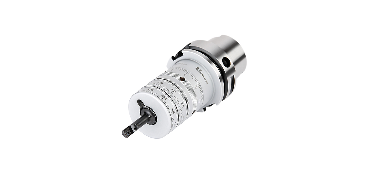
Increase productivity & performance in fine boring applications

High precision system for large volume production where fully automated fine boring applications with extremely tight tolerances are required.

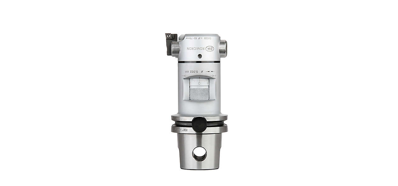
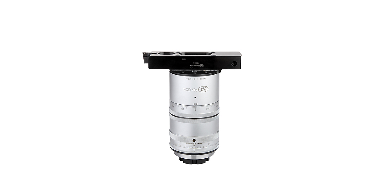
Covering a diameter range from 4–213mm (.1575–8.3858"), Romicron features a hole accuracy of up to IT6, hole cylindricity of up to 5 μm and hole position of up to 5 μm.

Applicable in any material, Romicron reduces setup time and scrap rates while increasing overall productivity and equipment efficiency.

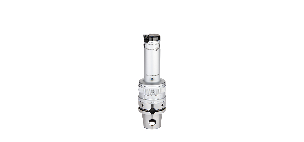
Existing machines can be easily retrofitted to automated insert wear compensation using the standard Closed-Loop-Boring Pin.

Using a probe, time-consuming control cuts, costly sister tooling, or insert changes in the presetting area can be eliminated.

Diameter adjustment can be done inside the machine.

Features & Benefits

  • Fits with any standard Kennametal ISO turning inserts, for a broad range of application and materials.
  • 100% mechanical system with micron adjustment by hand or fully automated, for fast and easy diameter adjustments.
  • Precise diameter adjustment, for scrap rate and set up time reduction.
  • One click, one micron. Each click on the diameter adjustment ring is a precise one micron adjustment on the radius. See, feel, and hear it.

Diameter Adjustment Process

  • A probe measures and communicates the actual diameter to the machine control.
  • The machine control calculates the difference between the actual and the target diameter and calculates the number of required clicks on the Romicron tool.
  • After that the spindle moves with the Romicron tool to the Closed-Loop Boring Pin. The pin can be installed anywhere on the table.
  • The table engages with one of the holes in the diameter adjustment ring.
  • The spindle rotates around its own axis and the calculated adjustment will be applied to the tool.
Select Filters
Filters
View filters in
Metric
Inch
Key Filters
Workpiece Material
Workpiece Material
  • P Steel (553)
    • P0
      Low-Carbon Steels, Long Chipping C < .25%; <125 HB; <530 N/mm^2 UTS (553)
    • P1
      Low-Carbon Steels, Short Chipping C < .25%; <125 HB; <530 N/mm^2 UTS (553)
    • P2
      Medium and High Carbon Steels C < .25%; <220 HB; <25 HRC; >530 N/mm^2 UTS (553)
    • P3
      Alloy Steels & Tool Steels C > .25%; <330 HB; <35 HRC; 600-850 N/mm^2 UTS (553)
    • P4
      Alloy Steels & Tool Steels C > .25%; 350-420 HB; 35-43 HRC; 850-1400 N/mm^2 UTS (553)
    • P5
      Ferritic, Martensitic, and PH Stainless Steels <330 HB; <35 HRC; 600-900 N/mm^2 UTS (553)
    • P6
      High Strength Ferritic, Martensitic, and PH Stainless Steels 350-450 HB; 35-43 HRC; 900-2400 N/mm^2 UTS (553)
  • M Stainless Steel (464)
    • M1
      Austenitic Stainless Steel 130-200 HB; <600 N/mm^2 UTS (464)
    • M2
      High Strength Austenitic Stainless and Cast Stainless Steels 150-230 HB; <25 HRC; >600 N/mm^2 UTS (464)
    • M3
      Duplex Stainless Steel 135-275 HB; <30 HRC; 500-1200 N/mm^2 UTS (464)
  • K Cast Iron (338)
    • K1
      Gray Cast Iron 120-290 HB; <32 HRC; 125-500 N/mm^2 UTS (337)
    • K2
      Low and Medium Strength CGI and Ductile Irons 130-260 HB; <28 HRC; <600 N/mm^2 UTS (337)
    • K3
      High Strength Ductile and Austempered Ductile Iron 180-350 HB; <43 HRC; >600 N/mm^2 UTS (337)
  • N Non-Ferrous Materials (212)
    • N1
      Wrought Aluminum (180)
    • N2
      Low-Silicon Aluminum Alloys and Magnesium Alloys Si <12.2% (193)
    • N3
      High-Silicon Aluminum Alloys Si >12.2% (100)
    • N4
      Copper, Brass, Zinc-based on machinability index range of 70-100 (212)
    • N5
      Nylon, Plastics, Rubbers, Phenolics, Resins, Fiberglass (206)
    • N6
      Carbon, Graphite Composites, CFRP (186)
    • N7
      MMC's (109)
  • S High-Temp Alloys (434)
    • S1
      Iron-Based, Heat-Resistant Alloys 160-260 HB; 25-48 HRC; 500-1200 N/mm^2 UTS (433)
    • S2
      Cobalt-Based, Heat-Resistant Alloys 250-450 HB; 25-48 HRC; 1000-1450 N/mm^2 UTS (433)
    • S3
      Nickel-Based, Heat Resistant Alloys 160-450 HB; <48 HRC; 600-1700 N/mm^2 UTS (433)
    • S4
      Titanium and Titanium Alloys 300-400 HB; 33-43 HRC; 900-1600 N/mm^2 UTS (403)
  • H Hardened Materials (101)
    • H1
      Hardened Materials 44-48 HRC (101)
    • H2
      Hardened Materials 48-55 HRC (101)
    • H3
      Hardened Materials 56-60 HRC (101)
    • H4
      Hardened Materials >60 HRC (101)
  • C CFRP Materials (194)
    • C1
      CFRP, CFRP / CFRP (186)
    • C2
      CFRP / Aluminium CFRP / Non-Ferrous (108)
Select First Choice
  • IN (25)
  • US (1)
Applications
Applications
  • Blind Hole Finishing Blind Hole Finishing (56)
  • Boring Boring (2)
  • Facing Facing (2)
  • ID Facing ID Facing (2)
  • Multiple Direction Cutting Multiple Direction Cutting (12)
  • Profiling Profiling (1)
  • Through Hole Finishing Through Hole Finishing (56)
  • Turning Turning (2)
Cutting Condition
Cutting Condition
  • Heavily Interrupted Cut (209)
  • Lightly Interrupted Cut (349)
  • Smooth Cut (553)
  • Varying Depth of Cut (353)
Tool Cutting Edge Angle
  • 90.0 (44)
  • 95.0 (2)
Tool Cutting Edge Angle Min to Tool Cutting Edge Angle Max
Connection Style
Connection Style
  • Whistle Notch 2 Front (12)
Cutting Edges Per Insert
  • 0.0 (5)
  • 1.0 (36)
  • 2.0 (359)
  • 3.0 (229)
  • 4.0 (72)
Cutting Edges Per Insert Min to Cutting Edges Per Insert Max
Internal Coolant Capability
Over All Length [L]
Over All Length [L]
  • 0.754 in (3)
  • 0.756 in (3)
  • 0.776 in (7)
  • 0.929 in (1)
  • 0.931 in (3)
  • 0.971 in (3)
  • 1.161 in (1)
  • 1.209 in (3)
  • 1.358 in (1)
  • 1.437 in (1)
  • 1.524 in (3)
  • 1.635 in (1)
  • 2.0 in (1)
  • 2.197 in (1)
  • 2.273 in (1)
  • 2.386 in (1)
  • 2.441 in (1)
  • 2.695 in (1)
  • 3.089 in (1)
  • 3.15 in (1)
  • 3.161 in (1)
  • 3.561 in (2)
Over All Length [L] Min to Over All Length [L] Max
Over All Length [L]
Over All Length [L]
  • 19.151 mm (3)
  • 19.201 mm (3)
  • 19.701 mm (7)
  • 23.6 mm (1)
  • 23.651 mm (3)
  • 24.651 mm (3)
  • 29.5 mm (1)
  • 30.701 mm (3)
  • 34.5 mm (1)
  • 36.5 mm (1)
  • 38.7 mm (3)
  • 41.5 mm (1)
  • 50.801 mm (1)
  • 55.801 mm (1)
  • 57.7 mm (1)
  • 60.6 mm (1)
  • 62.0 mm (1)
  • 68.45 mm (1)
  • 78.45 mm (1)
  • 80.0 mm (1)
  • 80.301 mm (1)
  • 90.45 mm (2)
Over All Length [L] Min to Over All Length [L] Max
Corner configuration
Corner Radius
Corner Radius
  • 0.002 in (10)
  • 0.004 in (104)
  • 0.007 in (27)
  • 0.008 in (182)
  • 0.015 in (20)
  • 0.016 in (342)
  • 0.031 in (317)
  • 0.047 in (9)
Corner Radius Min to Corner Radius Max
Corner Radius
Corner Radius
  • 0.05 mm (10)
  • 0.1 mm (104)
  • 0.176 mm (27)
  • 0.2 mm (182)
  • 0.375 mm (20)
  • 0.4 mm (342)
  • 0.8 mm (317)
  • 1.201 mm (9)
Corner Radius Min to Corner Radius Max
Corner Chamfer
Corner Chamfer
  • 0.0 mm (704)
Corner Chamfer Min to Corner Chamfer Max
Corner Chamfer
Corner Chamfer
  • 0.0 in (704)
Corner Chamfer Min to Corner Chamfer Max
Application
Minimum Depth of Cut
Minimum Feed
Minimum Feed
Grade Of Cutting Tool
  • K00379 (3)
  • K313 (95)
  • K420 (2)
  • K68 (91)
  • KB1345 (11)
  • KB1610 (86)
  • KB1630 (11)
  • KB5610 (85)
  • KB5625 (10)
  • KB5630 (11)
  • KB9610 (10)
  • KBH10 (7)
  • KBH20 (91)
  • KC250 (85)
  • KC5010 (148)
  • KC5025 (126)
  • KC525M (1)
  • KC5410 (101)
  • KC710 (86)
  • KC720 (85)
  • KC725M (2)
  • KC730 (134)
  • KC7310 (84)
  • KC732 (85)
  • KC8050 (85)
  • KC810 (85)
  • KC850 (105)
  • KC9010 (85)
  • KC9025 (85)
  • KC910 (85)
  • KC9105 (85)
  • KC9110 (85)
  • KC9120 (85)
  • KC9125 (85)
  • KC9225 (85)
  • KC9240 (85)
  • KC9240NEW (85)
  • KC9315 (85)
  • KC9320 (85)
  • KC9325 (85)
  • KC935 (87)
  • KC950 (85)
  • KC990 (85)
  • KCD25 (85)
  • KCK05 (89)
  • KCK15 (95)
  • KCK15B (91)
  • KCK20 (101)
  • KCK20B (92)
  • KCM15 (90)
  • KCM15B (89)
  • KCM25 (97)
  • KCM25B (93)
  • KCM35 (1)
  • KCP05 (88)
  • KCP10 (94)
  • KCP10B (96)
  • KCP25 (108)
  • KCP25B (106)
  • KCP25C (130)
  • KCP30 (86)
  • KCPK05 (85)
  • KCPK30 (2)
  • KCS10 (100)
  • KCS10B (100)
  • KCU10 (121)
  • KCU10B (156)
  • KCU25 (108)
  • KCU25B (140)
  • KD050 (84)
  • KD081 (2)
  • KD100 (86)
  • KD105 (84)
  • KD120 (84)
  • KD1400 (100)
  • KD1405 (85)
  • KD1425 (99)
  • KT125 (85)
  • KT150 (85)
  • KT175 (85)
  • KT315 (108)
  • KTP10 (89)
  • KU10 (85)
  • KU10T (85)
  • KU30T (85)
  • SPM5F2 (2)
  • SPMQMA (10)
Hand Of Tool
Hand Of Tool
  • R (12)
Wiper Insert
Wiper Insert
  • N (645)
  • Y (31)
Minimum Axial Groove Diameter
  • 4.0 mm (1)
  • 6.0 mm (2)
  • 8.5 mm (2)
  • 11.0 mm (2)
  • 13.5 mm (2)
  • 16.0 mm (1)
  • 19.0 mm (1)
  • 22.0 mm (1)
  • 25.0 mm (2)
  • 25.5 mm (1)
  • 29.5 mm (2)
  • 33.5 mm (1)
  • 34.0 mm (2)
  • 40.5 mm (1)
  • 42.0 mm (1)
  • 43.0 mm (1)
  • 45.5 mm (1)
  • 47.0 mm (1)
  • 49.0 mm (1)
  • 50.0 mm (1)
  • 52.0 mm (1)
  • 56.5 mm (1)
  • 60.0 mm (2)
  • 61.0 mm (1)
  • 65.0 mm (1)
  • 97.0 mm (1)
  • 100.0 mm (1)
  • 103.5 mm (1)
  • 110.0 mm (1)
  • 138.0 mm (3)
Minimum Axial Groove Diameter Min to Minimum Axial Groove Diameter Max
Minimum Axial Groove Diameter
  • 0.157 in (1)
  • 0.237 in (2)
  • 0.335 in (2)
  • 0.433 in (2)
  • 0.531 in (2)
  • 0.63 in (1)
  • 0.748 in (1)
  • 0.866 in (1)
  • 0.984 in (2)
  • 1.004 in (1)
  • 1.161 in (2)
  • 1.319 in (1)
  • 1.339 in (2)
  • 1.594 in (1)
  • 1.655 in (1)
  • 1.693 in (1)
  • 1.792 in (1)
  • 1.85 in (1)
  • 1.929 in (1)
  • 1.969 in (1)
  • 2.047 in (1)
  • 2.224 in (1)
  • 2.362 in (2)
  • 2.402 in (1)
  • 2.559 in (1)
  • 3.819 in (1)
  • 3.938 in (1)
  • 4.075 in (1)
  • 4.331 in (1)
  • 5.433 in (3)
Minimum Axial Groove Diameter Min to Minimum Axial Groove Diameter Max
Maximum Axial Groove Diameter
  • 0.276 in (1)
  • 0.354 in (1)
  • 0.374 in (1)
  • 0.453 in (1)
  • 0.473 in (1)
  • 0.551 in (1)
  • 0.572 in (1)
  • 0.65 in (1)
  • 0.669 in (1)
  • 0.768 in (1)
  • 0.886 in (1)
  • 1.004 in (1)
  • 1.319 in (1)
  • 1.713 in (1)
  • 2.559 in (1)
  • 3.938 in (1)
Maximum Axial Groove Diameter Min to Maximum Axial Groove Diameter Max
Maximum Axial Groove Diameter
  • 7.0 mm (1)
  • 9.0 mm (1)
  • 9.5 mm (1)
  • 11.5 mm (1)
  • 12.0 mm (1)
  • 14.0 mm (1)
  • 14.5 mm (1)
  • 16.5 mm (1)
  • 17.0 mm (1)
  • 19.5 mm (1)
  • 22.5 mm (1)
  • 25.5 mm (1)
  • 33.5 mm (1)
  • 43.5 mm (1)
  • 65.0 mm (1)
  • 100.0 mm (1)
Maximum Axial Groove Diameter Min to Maximum Axial Groove Diameter Max
Cutting Direction
Cutting Direction
  • B (2)
  • E (10)
Rake Angle Style
Rake Angle Style
  • NEUTRAL (ZERO) (11)
Maximum Bore Depth
Maximum Bore Depth
  • 0.562 in (1)
  • 0.803 in (1)
  • 0.854 in (1)
  • 1.041 in (1)
  • 1.201 in (1)
  • 1.28 in (1)
  • 1.415 in (1)
  • 1.516 in (1)
  • 1.573 in (1)
  • 2.165 in (1)
  • 2.362 in (2)
Maximum Bore Depth Min to Maximum Bore Depth Max
Maximum Bore Depth
Maximum Bore Depth
  • 14.275 mm (1)
  • 20.401 mm (1)
  • 21.701 mm (1)
  • 26.451 mm (1)
  • 30.5 mm (1)
  • 32.5 mm (1)
  • 35.95 mm (1)
  • 38.5 mm (1)
  • 39.95 mm (1)
  • 55.0 mm (1)
  • 60.0 mm (2)
Maximum Bore Depth Min to Maximum Bore Depth Max
Boring Bar Material
Boring Bar Material
  • S (4)
Front-End
Insert Shape
Insert Shape
  • C-DIAMOND/RHOMBIC 80 (474)
  • T-TRIANGLE 60 (239)
Cartridge Size
Cartridge Size
  • 1A. (1)
  • 1B. (1)
  • 1C. (1)
  • 1D. (1)
  • 1E. (1)
  • 1F. (1)
  • 1L. (1)
  • 1Y (1)
  • 2A. (1)
  • 2B. (1)
  • 2C. (1)
  • 2D. (1)
  • 2E. (1)
  • 2F. (1)
  • 2L. (3)
  • 2Y (1)
  • 3A. (1)
  • 3B. (1)
  • 3C. (1)
  • 3D. (1)
  • 3E. (1)
  • 3F. (2)
  • 3L. (1)
  • 3X (1)
  • 3Y (1)
Maximum Cutting Depth
  • 0.138 in (1)
  • 0.177 in (1)
  • 0.187 in (1)
  • 0.226 in (1)
  • 0.237 in (1)
  • 0.276 in (1)
  • 0.286 in (1)
  • 0.325 in (1)
  • 0.335 in (1)
  • 0.384 in (1)
  • 0.443 in (1)
  • 0.502 in (1)
Maximum Cutting Depth Min to Maximum Cutting Depth Max
Maximum Cutting Depth
  • 3.5 mm (1)
  • 4.5 mm (1)
  • 4.75 mm (1)
  • 5.75 mm (1)
  • 6.0 mm (1)
  • 7.0 mm (1)
  • 7.25 mm (1)
  • 8.25 mm (1)
  • 8.5 mm (1)
  • 9.75 mm (1)
  • 11.25 mm (1)
  • 12.75 mm (1)
Maximum Cutting Depth Min to Maximum Cutting Depth Max
Gage Length
Gage Length
  • 0.492 in (1)
  • 0.886 in (1)
  • 1.181 in (1)
  • 1.28 in (1)
  • 1.571 in (2)
  • 1.575 in (3)
  • 1.581 in (1)
  • 1.614 in (2)
  • 1.673 in (1)
  • 1.827 in (1)
  • 1.969 in (6)
  • 2.035 in (1)
  • 2.307 in (1)
  • 2.358 in (1)
  • 2.362 in (5)
  • 2.368 in (1)
  • 2.753 in (1)
  • 2.757 in (1)
  • 2.953 in (3)
  • 3.15 in (1)
  • 3.346 in (1)
  • 3.362 in (1)
  • 3.543 in (1)
  • 3.758 in (1)
  • 3.938 in (7)
  • 4.331 in (1)
  • 4.567 in (1)
  • 4.898 in (1)
  • 5.984 in (1)
Gage Length
Gage Length
  • 100 mm (7)
  • 50 mm (6)
  • 60 mm (5)
  • 40 mm (3)
  • 75 mm (3)
  • 41 mm (2)
  • 110 mm (1)
  • 116 mm (1)
  • 152 mm (1)
  • 30 mm (1)
  • 70 mm (1)
  • 80 mm (1)
  • 85 mm (1)
  • 90 mm (1)
  • 12.5 mm (1)
  • 22.5 mm (1)
  • 32.5 mm (1)
  • 39.901 mm (2)
  • 40.151 mm (1)
  • 42.5 mm (1)
  • 46.401 mm (1)
  • 51.7 mm (1)
  • 58.6 mm (1)
  • 59.901 mm (1)
  • 60.151 mm (1)
  • 69.9 mm (1)
  • 85.4 mm (1)
  • 95.45 mm (1)
  • 124.4 mm (1)
Insert Geometry
Shape
Shape
  • C-DIAMOND/RHOMBIC 80 (432)
  • T-TRIANGLE 60 (238)
Insert IC Size
Insert IC Size
  • 3.975 mm (51)
  • 5.551 mm (46)
  • 6.351 mm (278)
  • 9.525 mm (283)
  • 12.701 mm (7)
Insert IC Size Min to Insert IC Size Max
Insert IC Size
Insert IC Size
  • 0.156 in (51)
  • 0.219 in (46)
  • 0.25 in (278)
  • 0.375 in (283)
  • 0.5 in (7)
Insert IC Size Min to Insert IC Size Max
Cutting Edge Length
Cutting Edge Length
  • 4.025 mm (51)
  • 5.551 mm (5)
  • 5.65 mm (12)
  • 6.45 mm (167)
  • 9.625 mm (29)
  • 9.675 mm (193)
  • 10.951 mm (1)
  • 11.0 mm (110)
  • 12.9 mm (2)
  • 16.5 mm (90)
  • 22.0 mm (5)
Cutting Edge Length Min to Cutting Edge Length Max
Cutting Edge Length
Cutting Edge Length
  • 0.158 in (51)
  • 0.219 in (5)
  • 0.222 in (12)
  • 0.254 in (167)
  • 0.379 in (29)
  • 0.381 in (193)
  • 0.431 in (1)
  • 0.433 in (110)
  • 0.508 in (2)
  • 0.65 in (90)
  • 0.866 in (5)
Cutting Edge Length Min to Cutting Edge Length Max
Chip Breaker CBMD
Chip Breaker CBMD
  • FP (66)
  • FW (25)
  • HP (70)
  • K (20)
  • LF (263)
  • MF (46)
  • MP (21)
  • UF (15)
Cutting Tool Material
  • B H (49)
  • B L (59)
  • D P (71)
  • H T (70)
  • H W (646)
Tolerance Class
Tolerance Class
  • G (268)
  • H (51)
  • M (346)
Back-End
Connection Type
Connection Type
  • CYLINDRICAL (12)
System Size
System Size
  • BT40 (2)
  • BT50 (4)
  • CV40 (2)
  • CV50 (4)
  • DV40 (2)
  • DV50 (4)
  • HSK100A (5)
  • HSK63A (11)
  • KM40TS (4)
  • KM50 (2)
  • KM50TS (6)
  • KM63 (2)
  • KM63TS (1)
  • KM63XMZ (1)
  • KM80 (1)
  • KR32 (11)
  • KR50 (6)
  • KR63 (3)
  • KR80 (3)
Back-End Diameter
Back-End Diameter
  • 10.0 mm (5)
  • 16.0 mm (10)
  • 25.401 mm (1)
  • 31.75 mm (2)
  • 40.0 mm (4)
  • 44.45 mm (6)
  • 50.0 mm (8)
  • 63.0 mm (15)
  • 69.851 mm (12)
  • 80.0 mm (1)
  • 100.0 mm (5)
Back-End Diameter Min to Back-End Diameter Max
Back-End Diameter
Back-End Diameter
  • 0.394 in (5)
  • 0.63 in (10)
  • 1.0 in (1)
  • 1.25 in (2)
  • 1.575 in (4)
  • 1.75 in (6)
  • 1.969 in (8)
  • 2.48 in (15)
  • 2.75 in (12)
  • 3.15 in (1)
  • 3.938 in (5)
Back-End Diameter Min to Back-End Diameter Max
No filters matching ""
You are about to add to your My Solutions page. Do you want to proceed?
product-image
Please adjust the following properties from

ISO Catalog Number

ANSI Catalog Number

to find similar products.

The following files are available

Please select a file to download

Models

You should be logged to see your dashboard information
Session expired due to inactivity, please login again
The product/s () you were trying to add to the cart is/are not available, please contact customer service
item(s) successfully added to the cart
View Cart

. Please enter the desired qty for the material(s) you want to include in your promotion or Proceed Without Promotion and only your base materials will be added to the cart.

Minimum quantity should be

SAP Material Number ISO Catalog Number Grade    
Thank you for your registration, pending approval & completion of the registration, your access is currently limited. Full utilization of product search capabilities & collaboration space is available and will remain. Please allow 2 business days for registration completion.

You are about to leave the Solution building process.

Are you sure you want to leave?