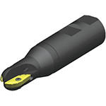
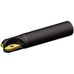
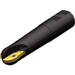
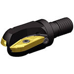
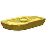
5505VX Ball Nose End Mills • Stellram
5505VX ball nose cutters and inserts are a state-of-the-art tooling system for roughing and semi-finishing profiles and complex contours. They are ideal for use on steel, alloyed steel, stainless steel, high-temperature alloys, and cast iron. The insert geometry is designed with chip grooves for better chip control. The 5505VX milling cutters feature a helical design and rigid fixation for increased speeds and feeds. They are available in Weldon shank for reinforced heavy machining, high volume of chip cutting, and have excellent chip control and evacuation. The cutters are also available with cylindrical shanks and in modular configurations.
- P Steel (44)
- P0Low-Carbon Steels, Long Chipping C < .25%; <125 HB; <530 N/mm^2 UTS(44)
- P1Low-Carbon Steels, Short Chipping C < .25%; <125 HB; <530 N/mm^2 UTS(44)
- P2Medium and High Carbon Steels C < .25%; <220 HB; <25 HRC; >530 N/mm^2 UTS(44)
- P3Alloy Steels & Tool Steels C > .25%; <330 HB; <35 HRC; 600-850 N/mm^2 UTS(44)
- P4Alloy Steels & Tool Steels C > .25%; 350-420 HB; 35-43 HRC; 850-1400 N/mm^2 UTS(44)
- P5Ferritic, Martensitic, and PH Stainless Steels <330 HB; <35 HRC; 600-900 N/mm^2 UTS(44)
- P6High Strength Ferritic, Martensitic, and PH Stainless Steels 350-450 HB; 35-43 HRC; 900-2400 N/mm^2 UTS(44)
- M Stainless Steel (44)
- M1Austenitic Stainless Steel 130-200 HB; <600 N/mm^2 UTS(44)
- M2High Strength Austenitic Stainless and Cast Stainless Steels 150-230 HB; <25 HRC; >600 N/mm^2 UTS(44)
- M3Duplex Stainless Steel 135-275 HB; <30 HRC; 500-1200 N/mm^2 UTS(44)
- S High-Temp Alloys (44)
- S1Iron-Based, Heat-Resistant Alloys 160-260 HB; 25-48 HRC; 500-1200 N/mm^2 UTS(44)
- S2Cobalt-Based, Heat-Resistant Alloys 250-450 HB; 25-48 HRC; 1000-1450 N/mm^2 UTS(44)
- S3Nickel-Based, Heat Resistant Alloys 160-450 HB; <48 HRC; 600-1700 N/mm^2 UTS(44)
- S4Titanium and Titanium Alloys 300-400 HB; 33-43 HRC; 900-1600 N/mm^2 UTS(44)
Face Milling (36)
Profile Milling (36)
Ramping (36)
Shoulder Ball Nose (36)
Shoulder Bottom Shoulder (36)
Shoulder Milling (36)
Shoulder Roughing (36)
Slot Ball Nose (36)
Slot Milling (36)
Slot Side (36)
- 0.625 in(3)
- 0.6299 in(2)
- 0.75 in(4)
- 0.787 in(1)
- 0.7874 in(2)
- 0.984 in(1)
- 0.9843 in(4)
- 1.0 in(3)
- 1.25 in(4)
- 1.2598 in(2)
- 1.2599 in(2)
- 1.5 in(2)
- 1.5748 in(1)
- 1.575 in(1)
- 1.969 in(2)
- 2.0 in(2)
- 15.874 mm(1)
- 15.875 mm(1)
- 15.876 mm(1)
- 16.0 mm(2)
- 19.0 mm(1)
- 19.05 mm(3)
- 20.0 mm(3)
- 25.0 mm(5)
- 25.4 mm(3)
- 31.75 mm(4)
- 32.0 mm(4)
- 38.1 mm(2)
- 40.0 mm(2)
- 50.0 mm(2)
- 50.8 mm(2)
- 16.0 mm(5)
- 16.6 mm(1)
- 19.05 mm(3)
- 20.0 mm(2)
- 20.3 mm(1)
- 25.0 mm(8)
- 32.0 mm(8)
- 38.1 mm(2)
- 40.0 mm(2)
- 50.8 mm(1)
- 51.0 mm(3)
- 0.6299 in(2)
- 0.63 in(3)
- 0.654 in(1)
- 0.75 in(3)
- 0.787 in(2)
- 0.799 in(1)
- 0.984 in(8)
- 1.26 in(8)
- 1.5 in(2)
- 1.575 in(2)
- 2.0 in(1)
- 2.008 in(3)
- 0.9843 in(1)
- 1.0 in(1)
- 1.181 in(1)
- 1.1811 in(1)
- 1.283 in(1)
- 1.378 in(3)
- 1.575 in(5)
- 1.9685 in(2)
- 2.0 in(1)
- 2.165 in(1)
- 2.347 in(1)
- 2.369 in(1)
- 2.559 in(2)
- 2.5591 in(2)
- 2.717 in(1)
- 2.9606 in(1)
- 3.0 in(1)
- 3.937 in(3)
- 3.9961 in(1)
- 4.0 in(2)
- 5.9055 in(1)
- 5.906 in(1)
- 5.9961 in(1)
- 6.08 in(1)
- 25.0 mm(1)
- 25.4 mm(1)
- 30.0 mm(2)
- 32.58 mm(1)
- 35.0 mm(3)
- 40.0 mm(5)
- 50.0 mm(2)
- 50.8 mm(1)
- 55.0 mm(1)
- 59.61 mm(1)
- 60.17 mm(1)
- 65.0 mm(4)
- 69.0 mm(1)
- 75.2 mm(1)
- 76.2 mm(1)
- 100.0 mm(3)
- 101.5 mm(1)
- 101.6 mm(2)
- 150.0 mm(2)
- 152.3 mm(1)
- 154.43 mm(1)
- 90.0 (36)
- Screw-On Connection (8)
- Straight-Cylindrical (11)
- Weldon (17)
- 2 (36)
- 1.6929 in(1)
- 1.709 in(1)
- 2.126 in(2)
- 2.441 in(2)
- 2.874 in(2)
- 4.173 in(1)
- 4.278 in(1)
- 4.567 in(1)
- 4.65 in(1)
- 5.0 in(1)
- 5.2803 in(1)
- 5.3228 in(1)
- 5.5 in(1)
- 5.9055 in(1)
- 6.2803 in(1)
- 6.2992 in(1)
- 6.685 in(1)
- 6.687 in(1)
- 6.6929 in(1)
- 6.693 in(1)
- 7.0 in(1)
- 7.0866 in(1)
- 7.874 in(1)
- 8.0 in(1)
- 8.6614 in(1)
- 8.6843 in(1)
- 9.055 in(1)
- 9.328 in(1)
- 9.8425 in(1)
- 9.843 in(2)
- 10.0 in(1)
- 10.079 in(1)
- 43.0 mm(1)
- 43.4 mm(1)
- 54.0 mm(2)
- 62.0 mm(2)
- 73.0 mm(2)
- 106.0 mm(1)
- 108.65 mm(1)
- 116.0 mm(1)
- 118.11 mm(1)
- 127.0 mm(1)
- 134.12 mm(1)
- 135.2 mm(1)
- 139.7 mm(1)
- 150.0 mm(1)
- 159.52 mm(1)
- 160.0 mm(1)
- 169.8 mm(1)
- 169.84 mm(1)
- 170.0 mm(2)
- 177.8 mm(1)
- 180.0 mm(1)
- 200.0 mm(1)
- 203.2 mm(1)
- 220.0 mm(1)
- 220.58 mm(1)
- 230.0 mm(1)
- 236.94 mm(1)
- 250.0 mm(3)
- 254.0 mm(1)
- 256.0 mm(1)
- 0.312 in(6)
- 0.375 in(5)
- 0.392 in(4)
- 0.492 in(9)
- 0.625 in(9)
- 0.768 in(3)
- 0.787 in(3)
- 1.0 in(5)
- 7.925 mm(6)
- 9.525 mm(5)
- 9.95 mm(4)
- 12.5 mm(9)
- 15.875 mm(9)
- 19.5 mm(3)
- 20.0 mm(3)
- 25.4 mm(5)
- R (36)
- N (8)
- 85.0 (36)
- 0.5512 in(1)
- 0.567 in(2)
- 0.689 in(1)
- 0.709 in(1)
- 0.718 in(1)
- 0.728 in(1)
- 0.732 in(1)
- 0.88 in(4)
- 0.896 in(1)
- 0.929 in(1)
- 1.1142 in(6)
- 1.4055 in(2)
- 1.4488 in(2)
- 1.503 in(1)
- 1.874 in(3)
- 14.0 mm(1)
- 14.4 mm(2)
- 17.49 mm(1)
- 18.0 mm(1)
- 18.24 mm(1)
- 18.5 mm(1)
- 18.6 mm(1)
- 22.34 mm(4)
- 22.77 mm(1)
- 23.6 mm(1)
- 28.3 mm(6)
- 35.7 mm(2)
- 36.8 mm(2)
- 38.17 mm(1)
- 47.6 mm(3)
- 7.391 mm(1)
- 8.534 mm(1)
- 9.0 mm(1)
- 11.0 mm(1)
- 14.097 mm(1)
- 17.0 mm(1)
- 18.0 mm(1)
- 22.25 mm(1)
- 0.291 in(1)
- 0.336 in(1)
- 0.3543 in(1)
- 0.4331 in(1)
- 0.555 in(1)
- 0.669 in(1)
- 0.7087 in(1)
- 0.876 in(1)
- H W (8)
- CYLINDRICAL (28)
- SCREW-ON (8)
- 13.0 mm(2)
- 15.87 mm(1)
- 18.0 mm(2)
- 19.04 mm(1)
- 19.05 mm(1)
- 20.0 mm(1)
- 21.0 mm(2)
- 25.0 mm(4)
- 25.39 mm(1)
- 25.4 mm(3)
- 29.0 mm(2)
- 31.75 mm(3)
- 32.0 mm(5)
- 38.1 mm(3)
- 40.0 mm(3)
- 50.0 mm(1)
- 50.8 mm(1)
- 0.5118 in(1)
- 0.512 in(1)
- 0.625 in(1)
- 0.709 in(2)
- 0.75 in(2)
- 0.7874 in(1)
- 0.827 in(2)
- 0.984 in(4)
- 1.0 in(4)
- 1.1417 in(2)
- 1.25 in(3)
- 1.26 in(5)
- 1.5 in(3)
- 1.575 in(3)
- 1.969 in(1)
- 2.0 in(1)
