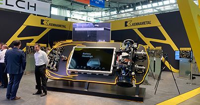
U.S customers, a 5% tariff surcharge will be added to your order for metal cutting products.

Essential Tips for Troubleshooting Indexable Milling

Three Kennametal Indexable Mills

Effective troubleshooting in indexable milling requires a systematic approach to identify and resolve issues. Common problems can include insert edge failure, subpar part appearance, machine noise or vibration and unusual cutter wear. To troubleshoot successfully, you must first accurately identify the issue and then implement corrective actions step-by-step.

There are typically five key areas of concern:

  • Cutting Tool Material (Grade)
  • Cutter/Adapter
  • Machine
  • Workpiece
  • Cutting Conditions

It is crucial to perform one corrective measure at a time to pinpoint the root cause effectively. Attempting multiple changes simultaneously may cause damage or lead to other hazardous conditions.

Edge Condition Problems and Solutions

Chipping

Normal flank wear lands have a fine, smooth wear pattern, while a land formed by chipping has a saw-toothed, uneven surface. If not detected soon enough, it may be perceived as depth-of-cut notching.

Chipping can also be caused by recutting chips. A good example of this would be a slotting operation where chip clearance or chip gullet space does not allow the chips to evacuate cleanly. In this instance, packing of the chips also occurs.

In most cases, by changing to a stronger grade and/or to a different edge preparation such as a larger hone or T-land, or from a 90˚ cutter geometry to a lead angle cutter geometry, will resolve the problem.

Indexable Milling Problem - Chipping on an insert

Problem

Cause

Solution

Chipping

System rigidity

Check system rigidity for proper part clamping.


Worn gibs/bearings

Correct worn gibs/bearings.


Improper cutter mounting

Check for improper cutter mounting.


Edge Prep

Use the largest hone or T-land possible.


Grade

Use a tougher grade.


Built-up Edge

Increase speed.


Feed

Reduce feed per tooth.


Recutting Chips

Choose cutter geometry with correct pitch for chip clearance.

Use air blast or coolant to remove chips.

Depth-of-Cut Notching

This appears when chipping or wearing at the depth-of-cut line on the rake face and flank of the insert.

Notching is primarily caused by the condition of the workpiece material and can include:

  • An abrasive workpiece skin of scale
  • Abrasive properties of high-temperature alloys like Inconel
  • A work-hardened outer layer resulting from a previous machining operation
  • Heat-treated material above 55 HRC
Indexable Milling Problem - Depth of cut notching on an insert

Problem

Cause

Solution

Depth-of-Cut Notching

Cutter geometry

Change to a lead angle cutter.


Grade

Use a more wear-resistant grade of carbide.


Feed

Reduce feed per tooth.


Speed

Reduce speed.


Edge-prep

Use honed or T-land inserts.


Programming

Vary depth of cut on very abrasive materials.

Thermal Cracks

These cracks run perpendicular to the insert’s cutting edge and are caused by the extreme temperature variations involved in milling. In one revolution of a milling cutter, the insert starts to cut and the temperature quickly rises as the insert enters the cut. The varying chip thickness also changes the temperature throughout the cut. When the insert comes out of the cut, air or coolant flow rapidly cools the insert before it reenters the cut.

The proper coolant application is crucial in milling operations to manage temperature and reduce thermal cracking.

Indexable Milling Problem - Thermal cracks on an insert

Problem

Cause

Solution

Thermal Cracks

Speed and Feed

Reduce cutting edge temperature by reducing the cutting speed and possibly the feed per tooth.


Coolant

Shut off coolant.


Grade

Use coated grade designed for wet milling.

Edge Build-Up

This condition involves the adhesion of layers of workpiece material to the top surface of the insert. Hardened pieces of the adhered material periodically break free, leaving an irregularly shaped depression along the cutting edge. This causes damage to the part and insert. Cutting forces also will be increased due to built-up edge.

Indexable Milling Problem - Built up edge on an insert

Problem

Cause

Solution

Built-up Edge

Speed

Increase SFM (Surface Feet per Minute).


Feed

Increase feed per tooth.


Coolant

Use mist or flood coolant to avoid chips sticking to the insert when machining stainless steel and aluminum alloys.


Grade

Use sharp edge PVD inserts.

Higher speeds require diamond-tipped inserts or diamond-coated inserts on certain non-ferrous alloys.


Edge-prep

Use sharp edge, positive rake PVD inserts, or polished inserts.

Crater Wear

A relatively smooth, regular depression is produced on the insert’s rake face. Crater wear occurs in two ways:

  1. Material adhering to the insert’s top surface is dislodged, carrying away minute fragments of the top surface of the insert.
  2. Frictional heat builds up from the flow of chips over the top surface of the insert. Eventually, this heat buildup softens the insert behind the cutting edge and removes minute particles of the insert until a crater forms. Crater wear is rarely encountered in milling but can appear when machining certain steel and cast iron alloys. If crater wear becomes severe, there is a risk that the cutting edge will break, destroying the insert.
Indexable Milling Problem - Crater wear on an insert

Problem

Cause

Solution

Crater Wear

Grade

Use a more wear-resistant grade.


Speed

Reduce cutting speed.


Edge-prep

Use smaller T-land or increase feed to proper range for T-land.

Flank Wear

Uniform flank wear is the preferred method of insert failure because it can be predicted. Excessive flank wear increases cutting forces and contributes to poor surface finish. When wear occurs at an unacceptable rate or becomes unpredictable, the key elements that must be investigated are speed, feed, grade, and insert/cutter geometry.

NOTE: Inserts should be indexed when roughing (0,38 to 0,50 mm flank wear is reached) and finishing (0,25 to 0,38 mm flank wear or sooner).

Indexable Milling Problem - Flank wear on an insert

Problem

Cause

Solution

Flank Wear

Speed

Check this area first. Recalculate SFM (Vc) to assure correctness.

Speed should be reduced without changing feed per tooth.


Feed

Increase feed per tooth (feed should be high enough to avoid the pure rubbing, which occurs with small chip thickness).


Grade

Use a more wear-resistant grade.

Change to a coated grade if you are now using an uncoated grade.


Insert Geometry

Inspect insert to determine if proper style is being used in the cutter.

Multiple Factors

When wear, chipping, thermal cracking, and breakage occur at once, the machine operator must look beyond the normal feed, speed, and depth-of-cut adjustments to find the root cause of the problem. Speed, feed and depth-of-cut parameters should be re-examined for accuracy, but the system’s rigidity should also be closely inspected for loose or worn parts as well.

Indexable Milling Problem - Multiple Factors on an insert

Problem

Cause

Solution

Multiple Factors

System Rigidity

Check system for loose cutter mounting.

Improve fixture and cutter rigidity.

Check for worn hardware or improper insert installation.

Reduce the gauge length of the cutter and arbor assembly.


Feed

Reduce feed rate to relieve cutting forces.


Cutter Geometry

If possible, use a lead angle cutter to redirect cutting forces away from the insert nose.


Insert/Grade

If possible, use a larger nose radius.

Use T-land insert.

Use a tougher grade of carbide.

The Importance of Insert Geometry

Different insert geometries can significantly impact milling performance and wear patterns.

Key considerations include:

  • Rake Angle: Positive rake angles reduce cutting forces and improve chip flow but may be less robust in heavy cuts. Negative rake angles offer greater strength and are better for tough materials.
  • Lead Angle: An insert’s lead angle can distribute cutting forces more evenly, reducing the risk of notching and improving surface finish.
  • Chipbreakers: Designed to control chip formation and evacuation, different chip breaker designs can enhance performance in specific materials and cutting conditions.

Troubleshoot Matrix for Advanced Cutting Tool Materials

This matrix explains the specific areas where advanced cutting tool materials perform differently from uncoated and coated carbide grades during the troubleshooting identification process.

Cutting Tool Material

Problem

Solution

Comments

Cermets

KT530M

Chipping

  • Reduce feed per insert
  • Turn off coolant
  • Apply hone or T-land insert
  • Excellent resistance to built-up edge.
  • Dry milling grades, do not use coolant.
  • KT530M is noted for maximum toughness and edge chipping resistance at moderate speeds and medium chip loads.

Breakage (Fracture)

  • Reduce depth of cut and chip load
  • Increase speed
  • Apply hone or T-land insert

Sialon
Kyon 1540
Kyon 2100

Depth-of-Cut Notch

  • Reduce hone or size of T-land edge preparation
  • Pre-chamfer part to eliminate stress points on cutting edge of insert
  • Vary depth of cut
  • Excellent for machining nickel-base materials over 35 HRC.
  • Available in positive rake inserts.
  • Run dry – no coolant.
  • Works well on PH stainless steels.
  • Use KY1540 at less than 600 m/min.

Minor Chipping

Minor chipping is normal, especially on Inconel

Flank Wear

Use 0.2 mm as indexing criterion

Fracture

Do not over-torque clamping

Silicon Nitride

Kyon 3500

Flank Wear

  • Reduce speed
  • Increase feed
  • Use without coolant.
  • Will provide optimum combination of increased toughness and wear resistance in high-speed machining of cast irons.
  • Wide range of Vc.
  • Kyon 3500 is your first choice for maximum toughness and edge chipping resistance at high-speed and heavy-to moderate feeds.

Chipping

  • Change edge preparation
  • Reduce chip load

Breakage

  • Reduce depth of cut
  • Use thicker inserts
You are about to add to your My Solutions page. Do you want to proceed?
Select the destination where you want to move to.
New Folder
    • Applied Filters:
    • Clear All

product-image
Please adjust the following properties from

ISO Catalog Number

ANSI Catalog Number

to find similar products.

The following files are available

Please select a file to download

Models

You should be logged to see your dashboard information
Session expired due to inactivity, please login again
The product/s () you were trying to add to the cart is/are not available, please contact customer service
item(s) successfully added to the cart
View Cart

. Please enter the desired qty for the material(s) you want to include in your promotion or Proceed Without Promotion and only your base materials will be added to the cart.

Minimum quantity should be

SAP Material Number ISO Catalog Number Grade  

You are about to leave the Solution building process.

Are you sure you want to leave?

Standard

ALL

Material

Select a Value

Hardness

--

Hardness Scale

--

Permitted Groups :

Group

SubGroup

Hardness (HB)

Hardness (HRC)