List Price
/each
Discount
Your Price
/each
Sold in pkg. of 0Adjusted to meet the minimum package size.
Minimum qty: 0Adjusted to meet the minimum quantity requirement.
In StockThis item is no longer availableLonger Delivery


 Ramping: Blank
 Slotting: Square End
 Side Milling/Shoulder Milling: Square End
 Tool Dimensions: Flute Configuration: 3
 Helix Angle: 35°
 Corner Style: Corner Radius
Downloaded file will be available after import in the {{cadTool}} tool library.
| Material Number | 6441025 |
| ISO Catalog ID | RFDD0375Y3AQA |
| ANSI Catalog ID | RFDD0375Y3AQA |
| Grade | KCPM15 |
| Adapter Style Machine Side | DUO-LOCK |
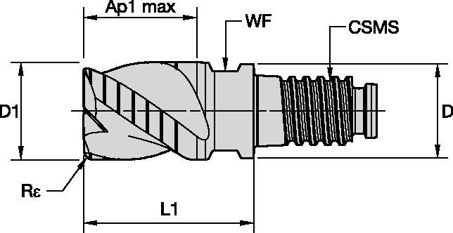
| [D] Adapter / Shank / Bore Diameter | 9.125 mm |
| [D] Adapter / Shank / Bore Diameter | 0.3593 in |
| [L1] Gage Length | 16.64 mm |
| [L1] Gage Length | 0.6551 in |
| [CSMS] System Size Machine Side | DL10 |
| [WF] Width of Flat | 8 mm |
| [WF] Width of Flat | 0.315 in |
| [Re] Corner Radius | 0.375 mm |
| [Re] Corner Radius | 0.015 in |
| [Z] Number of Flutes | 3 |
| [D1] Effective Cutting Diameter | 9.525 mm |
| [D1] Effective Cutting Diameter | 0.375 in |
| [AP1MAX] 1st Maximum Cutting Depth | 7.144 mm |
| [AP1MAX] 1st Maximum Cutting Depth | 0.2813 in |
Ramping: BlankSlotting: Square EndSide Milling/Shoulder Milling: Square EndTool Dimensions: Flute Configuration: 3Helix Angle: 35°Corner Style: Corner RadiusGrades

KCPM15
Coated carbide grade with thick PVD coating and optimized chemistry and process for increased wear resistance. Outstanding protection in milling stainless steel to mitigate crater, DOCN (depth-of-cut notching), and flank wear. Excellent performance up to 52 HRC.
Create Solution to calculate Feeds and Speeds
After creating a solution just choose the Feeds & Speeds icon and our system will provide recommendations. You can customize the information by adding your machine and specifications or make adjustments using the sliders.
| Material | 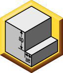 | 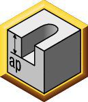 | straight short | conical medium | conical long | Recommended feed per tooth (IPT = inch/th) for side milling (A). For slotting (B), reduce IPT by 20%. | ||||||||||||
| A | B | KCPM15 | KCPM15 | KCPM15 | D1 | |||||||||||||
| Cutting Speed | Cutting Speed | Cutting Speed | frac. | 3/8 | 1/2 | 5/8 | 3/4 | |||||||||||
| ap | ae | ap | Min | Max | Min | Max | Min | Max | dec. | 0.3750 | 0.5000 | 0.6250 | 0.7500 | |||||
| P | 0 | 0.75 x D | 0.5 x D | 0.5 x D | 490 | – | 660 | 441 | – | 594 | 441 | – | 594 | IPT | 0.0023 | 0.0029 | 0.0034 | 0.0037 |
| 1 | 0.75 x D | 0.5 x D | 0.5 x D | 490 | – | 660 | 441 | – | 594 | 441 | – | 594 | IPT | 0.0023 | 0.0029 | 0.0034 | 0.0037 | |
| 2 | 0.75 x D | 0.5 x D | 0.5 x D | 460 | – | 620 | 414 | – | 558 | 414 | – | 558 | IPT | 0.0023 | 0.0029 | 0.0034 | 0.0037 | |
| 3 | 0.75 x D | 0.5 x D | 0.5 x D | 390 | – | 520 | 351 | – | 468 | 351 | – | 468 | IPT | 0.0019 | 0.0025 | 0.0029 | 0.0033 | |
| 4 | 0.75 x D | 0.4 x D | 0.5 x D | 300 | – | 490 | 270 | – | 441 | 270 | – | 441 | IPT | 0.0017 | 0.0022 | 0.0026 | 0.0029 | |
| 5 | 0.75 x D | 0.5 x D | 0.5 x D | 200 | – | 330 | 170 | – | 281 | 160 | – | 264 | IPT | 0.0016 | 0.0020 | 0.0023 | 0.0026 | |
| 6 | 0.75 x D | 0.4 x D | 0.5 x D | 160 | – | 250 | 136 | – | 213 | 128 | – | 200 | IPT | 0.0013 | 0.0016 | 0.0019 | 0.0021 | |
| M | 1 | 0.75 x D | 0.4 x D | 0.5 x D | 300 | – | 380 | 240 | – | 304 | 210 | – | 266 | IPT | 0.0019 | 0.0025 | 0.0029 | 0.0033 |
| 2 | 0.75 x D | 0.4 x D | 0.5 x D | 200 | – | 260 | 160 | – | 208 | 140 | – | 182 | IPT | 0.0016 | 0.0020 | 0.0023 | 0.0026 | |
| 3 | 0.75 x D | 0.4 x D | 0.5 x D | 200 | – | 230 | 160 | – | 184 | 140 | – | 161 | IPT | 0.0013 | 0.0016 | 0.0019 | 0.0021 | |
| K | 1 | 0.75 x D | 0.5 x D | 0.5 x D | 390 | – | 490 | 351 | – | 441 | 351 | – | 441 | IPT | 0.0023 | 0.0029 | 0.0034 | 0.0037 |
| 2 | 0.75 x D | 0.5 x D | 0.5 x D | 360 | – | 460 | 324 | – | 414 | 324 | – | 414 | IPT | 0.0019 | 0.0025 | 0.0029 | 0.0033 | |
| 3 | 0.75 x D | 0.4 x D | 0.5 x D | 360 | – | 430 | 324 | – | 387 | 324 | – | 387 | IPT | 0.0016 | 0.0020 | 0.0023 | 0.0026 | |
| H | 1 | 0.75 x D | 0.2 x D | 0.3 x D | 260 | – | 460 | 208 | – | 368 | 156 | – | 276 | IPT | 0.0017 | 0.0022 | 0.0026 | 0.0029 |
| End Mill Tolerances | |
| D1 | tolerance d11 |
| 13/32 | -0.002/-0.0063" |
| 23/32 | -0.026/ -0.0077" |
I have read and accepted the Terms & Conditions of use


ISO Catalog Number
ANSI Catalog Number
to find similar products.Please select a file to download
Models
Product data
. Please enter the desired qty for the material(s) you want to include in your promotion or Proceed Without Promotion and only your base materials will be added to the cart.
Minimum quantity should be
| SAP Material Number | ISO Catalog Number | Grade |
|---|
You are about to leave the Solution building process.
Are you sure you want to leave?